


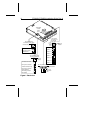


Attaching cables
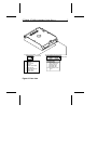
Refer to Figure 1 on page 6 and Figure 2 on page 7 for the
locations of the connectors and jumper blocks.
1. Turn off the system power.
2. Put on a grounded wrist strap.
3. Connecting a remote LED. Remote LED pins are located on
two separate jumper blocks: the options jumper block and the
user-configuration jumper block. Attach a two-pin remote LED
connector to either jumper block, as follows:
• User-configuration jumper block: pins 9 and 10
• Options jumper block: pins 7 and 8
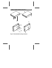
4. Synchronizing drive spindles (disc arrays only). You can
synchronize the spindle motors of an array of drives by con-
necting a twisted pair to each drive. The maximum cable
length is 6 feet (1.8 meters).
Spindle synchronization pins are located on two separate
jumper blocks—the options jumper block and the user-con-
figuration jumper block. Use either jumper block to synchro-
nize an array of drives, as follows:
• User-configuration jumper block. Use one strand of the
twisted pair to connect together pin 7 of the user-configura-
tion jumper block of each drive. Use the other strand to
connect together pin 8 of the user-configuration jumper
block of each drive.
• Options jumper block. Use one strand of the twisted pair
to connect together pin 5 of the options jumper block of each
drive. Use the other strand to connect together pin 6 of the
options jumper block of each drive.
5. Attaching the power cable. Attach a system power cable to
the drive power connector.
ST3390N, ST3655N Installation Guide, Rev. A 5