


Page 18- VisionGaurd
System
Wiring
6-Pin Starter Harness
Pin 1 RED WIRE A: Main Power Input A (+). Connect to the battery or constant power wire at the ignition
switch with a minimum 25 Amp supply. Remove the fuse until the installation is complete and all wiring
is checked.
Pin 2 RED WIRE B: Main Power Input B (+). Connect to the battery or constant power wire at the ignition
switch with a minimum 25 Amp supply. Note: if connecting at the ignition switch it is highly
recommended to use separate power wires for each Red wire, each with a minimum 25A supply.
Remove the fuse until the installation is completed and all wiring is checked.
Pin 3 BROWN WIRE: Second Ignition Output (+). The Brown wire provides +12V for a second ignition
wire. This wire may instead be programmed for use as a second accessory or second starter wire.
Pin 4 ORANGE WIRE: Accessory Output (+). Connect to the accessory wire coming from the ignition
switch that supplies power to the heater/air-conditioner. Some cars may have multiple accessory wires.
Pin 5 YELLOW WIRE: Ignition Output (+). Connect to the main ignition wire that provides +12V when the
ignition is on and while cranking the starter.
Pin 6 VIOLET WIRE: Starter Output (+). Connect to the the vehicle’s starter wire.
20-Pin Main Harness
Pin 1 GREEN/WHITE WIRE: Brake Input (+). Connect to the wire that shows +12V when pressing the
brake. The Green/white wire is a safety shutdown wire that must be connected.
Pin 2 BLACK/GRAY WIRE: Tach Input. Connect to the vehicle’s tach wire or a fuel injector wire if the
tachless mode does not provide satisfactory operation.
Pin 3 WHITE/RED WIRE: Auxiliary 2 Output (-) 500 mA. Connect to a relay or module for an optional
feature such as power window activation, etc. the output may be programmed for momentary, timed,
or latched operation.
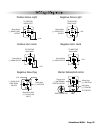
Pin 4 BLACK/WHITE WIRE: Dome Light Output (-) 500 mA. Connect to the wire that activates the
vehicle’s dome light, usually the door pin switch wire. (see Green and Violet door trigger wires).
NOTE: Must use relay (see page 25 negative dome light relay diagram)
Pin 5 YELLOW WIRE: +12V Ignition Input. The Yellow wire must connect to a main ignition wire at the
ignition harness. This wire must show +12V when the ignition is on and while cranking the starter. The
voltage must not drop when the car is starting.
Pin 6 BLUE/YELLOW WIRE: Glow Plug Input (+). For vehicles equipped with diesel engines the
Blue/yellow wire must be connected to the wait-to-start light in the gauge panel. This wire will show
+12V when the light is on, and ground when the light turns off. If the wait-to-start wire shows ground
when the light is on, a relay must be installed (see wiring diagrams).
Pin 7 BLUE/WHITE WIRE: Passenger Unlock Output (-) 500 mA. Connect to a relay to unlock the
passenger doors when the system is configured for Driver Priority Unlocking.
Pin 8 BLUE/ORANGE WIRE: Ground When Running Output (-) 500 mA. Connect to an optional factory
security bypass module if required.
Pin 9 BLACK WIRE: Ground Input (-). The Black wire must connect to a solid chassis ground. Clean away
any paint or dirt to insure the best possible ground.
Pin 10 RED WIRE: Module Power Input (+). Connect to a constant source of +12V.
Pin 11 VIOLET WIRE: Positive Door Input (+). Connect to the door switch circuit wire that shows +12V