


Rosen Aviation
Document Number: 100923
Revision: C
Date: 9/18/08
Template: 4.2.3-6-FM; Revision A; 16 May, 2005
Page 5 of 21
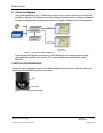
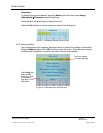
2.1. Connection Diagram
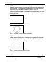
The typical installation of the 7” WideScreen monitor is one or more monitors on an arm mount,
sidewall, or bulkhead. The following connection diagram illustrates how to configure the displays
to create a complete cabin entertainment system or integrate a display into an existing system.
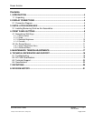
Figure 1 Typical arm mount installation
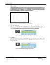
These displays are typically connected to a video distribution unit, which provides a single
composite video signal to each monitor. The video distribution box performs the source
selection.
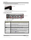
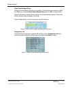
3. INSTALLATION GUIDELINES
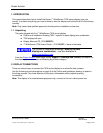
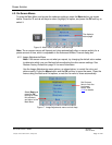
Ensure that when plugging the arm into the base receptacle, the set screw in the base follows the
arm’s keyed slot and the connection is not forced.
Figure 2 Arm mount base receptacle
Slot
Set screw