


Rosen Aviation
Document Number: 100923
Revision: C
Date: 9/18/08
Template: 4.2.3-6-FM; Revision A; 16 May, 2005
Page 18 of 21
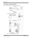
6. TECHNICAL REFERENCES AND SUPPORT
The Outline & Installation drawing is also available at
www.rosenaviation.com.
From the Rosen Aviation home page, select Support Drawings and Pinouts, and search for the
drawing by model number or browsing by product category.
6.1. Troubleshooting
If the display does not function properly, refer to the following troubleshooting tips for symptoms
and possible solutions before contacting Rosen Aviation field support.
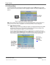
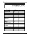
Table 2 Troubleshooting tips and solutions
Problem
Possible Solutions
Power LED does not illuminate
(neither RED nor GREEN)
Verify pinout to base receptacle is correct (power input
connection)
Verify voltage to monitor is correct
Check the arm and base receptacle connectors for damaged
pins
Check for damaged pins in base
Monitor not turned on
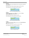
Power LED is red
If pushing the power button does not turn the power LED
green, the display failed. Please call customer service.
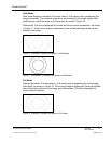
Power LED is green but no
video displays (black screen)
Verify pinout to base receptacle is correct.
Check the arm and base receptacle connectors for damaged
pins (video input connection)
Verify that video source is on and displaying video
Verify that video source is in play mode
Verify video signal at monitor connector
Check for damaged pins in base
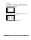
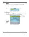
Distorted image
Verify that the pinout is correct
Verify that the signal is present and accurate
Examine the display for pinched or damaged cables.
Verify NTSC input
Check for damaged pins in base
Ensure the internal system temperature is not above or
below the allowed parameters.
Try changing the scaling mode. See Scale on page 7 for
more information.