


10
DYNAMIXEL
DX-Series
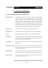
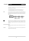
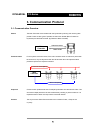
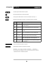
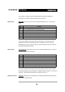
0XFF 0XFF Two 0XFF bytes indicate the start of a packet.
ID ID of the Dynamixel which is returning the packet.
LENGTH The length of the Status Packet. The value is “Parameter number (N) + 2”.
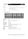
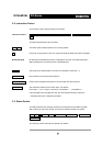
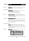
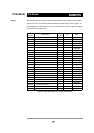
ERROR Dynamixel communication error flags. The meaning of each bit is as follows:
PARAMETER0…N Used when additional information is required.
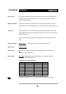
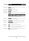
CHECK SUM SUM Calculation method of ‘Check Sum’is as follows:
Check Sum = ~( ID + Length + Instruction + Parameter1 + … Parameter N )
If the calculated value is bigger than 255, the lower byte becomes the checksum.
~ represents the Not or complement operation
Bit Name Details
Bit 7 0 -
Bit 6 Instruction Error
Set to 1 if an undefined instruction is given without the
reg_write instruction.
Bit 5 Overload Error Set to 1 if the specified torque can't control the load.
Bit 4 Checksum Error
Set to 1 if the checksum of the intruction packet is
incorrect
Bit 3 Range Error Set to 1 if the instruction is out of the usage range.
Bit 2
Overheating
Error
Set as 1 if the internal temperature of Dynamixel is out of
the operative range as set in the control table.
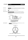
Bit 1 Angle Limit Error
Set as 1 if the goal position is set outside of the range
between CW Angle Limit and CCW Angle Limit
Bit 0
Input Voltage
Error
Set to 1 if the voltage is out of the operative range set in
the control table.