


9
DYNAMIXEL
DX-Series
3-2. Instruction Packet
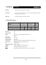
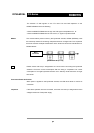
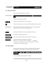
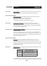
The structure of the Instruction Packet is as follows:
Instruction Packet OXFF 0XFF ID LENGTH INSTRUCTION PARAMETER1 …PARAMETER N CHECK
SUM
The packet byte definitions are as follows.
0XFF 0XFF Two 0XFF bytes indicate the start of an incoming packet.
ID Unique ID of a Dynamixel. The ID can range from 0X00 to 0XFD (254 IDs are available)
Broadcasting ID ID ID 0XFE is the Broadcast ID which is assigned to all of the connected Dynamixel’s.
Status packets will not be returned with a broadcasting ID.
LENGTH The length of the Status Packet. The value is “Parameter number (N) + 2”
INSTRUCTION The instruction for the Dynamixel to perform.
PARAMETER0…N Used if there is additional information to be sent other than the Instruction.
CHECK SUM The calculation method for the ‘Check Sum’ is as follows:
Check Sum = ~( ID + Length + Instruction + Parameter1 + … Parameter N )
If the calculated value is bigger than 255, the lower byte becomes the checksum.
~ represents the Not or complement operation
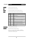
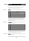
3-3. Status Packet
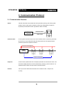
The Status Packet is the response packet from the Dynamixel to the Main Controller
after receiving an instruction packet. The structure of Status Packet is as follows :
OXFF 0XFF ID LENGTH ERROR PARAMETER1 PARAMETER2…PARAMETER N
CHECK SUM
The meaning of each byte within the packet is as follows :