


GPS-20 Operating Manual
Rikaline
Rikaline Marketing Corp.
5F-1, 125, Roosevelt Road, Sec. 5, Taipei, Taiwan 116
Tel: ++886 2 2934 5456 Fax: ++886 2 2934 4373 E-Mail: info@rikaline.com.tw
web: www.rikaline.com.tw
9
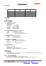
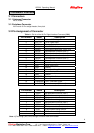
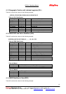
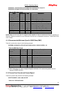
Tracking 220 170 160
CPU 360 33 29
Trickle 420 0.55 0.55
Note: Table 1-4 does not include the external antenna power, which must be controlled from the system
power supply.
3.4 Push-to-Fix Description
The purpose of Push-to-Fix mode is to support applications where a position fix is only required when
requested by the user (or the application). To support this, the board is left in the Trikle state until
commanded to generate a fix.
3.4.1 Power-on State
In this state, the receiver calculates the position once, collects the ephemeris, and calibrates the RTC
before going back to the Trickle State.
3.4.2 Trickle State
In this state only the RTC is running. The supply current is typically <500uA, which includes the
standby current of the GSP2e and CPU.
There are three events that can happen which effectively return the CPU to normal operation:
3.4.3 Power-on
If power is removed, then re-applied to the board a reset signal is generated by the CPU supervisor.
After the reset has been removed, the CPU will start up, get a fix and return to Trickle State. This
typically takes 2 to 6 seconds.
3.4.4 Ephemeris Collection
Every 30 minutes the GSP2e WAKEUP signal is activated, wake up the CPU to calculate a fix, collect
a new ephemeris, calibrate the RTC and then go to the Trickle State.
3.4.5 User Requested Fix
With each user request of a fix, the CPU will wake up by toggling PBRES low (pin 5 of the digital
interface connector). The CPU is restarted and (following a Snap Start) a fix is calculated. Before
going back to Trickle State, the CPU will check the ephemeris and the RTC calibration.
Note – The CPU will restart ~ 200-600 mSec after the PBRES input is brought high.
3.5 SRAM DATA BACKUP Description