


GPS-20 Operating Manual
Rikaline
Rikaline Marketing Corp.
5F-1, 125, Roosevelt Road, Sec. 5, Taipei, Taiwan 116
Tel: ++886 2 2934 5456 Fax: ++886 2 2934 4373 E-Mail: info@rikaline.com.tw
web: www.rikaline.com.tw
8
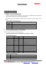
on. To achieve the faster start-up offered by a hot start or warm start, either a battery backup input
must be connected or a recharge battery installed
.
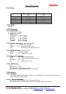
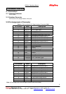
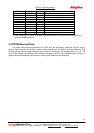
Table 1-3 Backup Battery Voltage Range
Board MIN MAX
GPS-20 2.5 3.3
With a 3.3V Lithium-Ion (2.3mAh) rechargeable .To maximize battery lifetime (3~5 years), the battery
voltage should not exceed 3.3V.
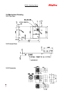
3.2.13 GPIO Functions
Several I/Os of CPU are connected to the digital interface connector for consumer applications and
are labeled GPIOA to GPIOI.
3.2.14 JTAG Functions
The JTAG interface provides a standard development/debugging interface. A simple header connects
to a variety of the off-the-shelf emulators to provide single-step, trap and access to all the internal
registers of the GSP2e.
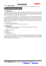
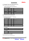
3.3 TricklePower
TM
Description
The GPS-20 design includes all the functionality necessary to implement the SiRF TricklePower
mode of operation. In this mode, the lowest average power dissipation is achieved by powering down
the board (after a position is determined) in such a manner that when it is turned back on it can
recomputed a position fix in the shortest amount of time. Standard TricklePower operates in three
states
3.3.1 Tracking State
In this state, the board is fully powered, tracking satellites, and gathering data.
3.3.2 CPU State
In this mode, the GRF2i has been turned off which removes the clock to the GSP2e. Without a clock,
the GSP2e is effectively powered down (although the RTC keeps running). The CPU would switch to
ECLK and kept running to process the GPS data until a position fix is determined and the result has
been transmitted by the serial communication interface.
3.3.3 Trickle State
In this state, the CPU is in a low power standby state and the receiver clocks are off with only the
RTC clock active. After a set amount of time, the RTC generates an NMI signal to wake up the
ARM-7 microprocessor and reset the receiver back to tracking state.
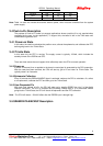
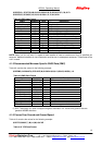
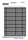
The default time for each TricklePower mode and the approximate current consumed (in each mode)
is shown in Table 1-4. For example, the TricklePower duty cycle (20%), the average receiver power
dissipation is approximately 165mW (60mA @ 3.3V) while maintaining one-second update rate.
Table 1-4 TricklePower
TM
Power Consumption
Mode
Time
Msec
+5V
Current
mA
+3.3V
Current
mA