


GPS-22 Operating Manual
Rikaline
Specifications subject to change without prior notice
Rikaline International Corp. 14F, 171, ChengGong Rd., Sanchong City, Taipei 241, Taiwan, R. O.C
Tel: ++886 2 8973-1899 Fax: ++886 2 8973-1896 E-Mail: info@rikaline.com.tw web: www.rikaline.com.tw
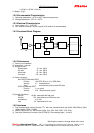
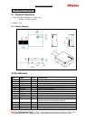
1) All I/Os on the Data Interface are related to VCC (3 to 3.6 Volts) and GND levels.
2) ON/OFF: control the GPS engine “ON” or “OFF”. If this pin is pulled “HIGH” whenever a reset
condition occurs or if it is turned “HIGH” during operating, the GPS engine is turned “ON”. If this pin is
pulled “LOW” whenever a reset condition occurs, the GPS engine is not started. If this pin is turned
“LOW” when in operating, the GPS engine is turned “OFF”. When ON/OFF is “LOW”, the on/off state can
be superseded with the PXEMaRT manufacturer specific NMEA sentence on RXA, as defined below.
3) RXA and TXA: The Serial NMEA data port (RXA and TXA) is an asynchronous serial port (UART).
4) USPED: USPED “HIGH”: 9600 Baud rate, 8 bit data, no parity check, 1 stop bit and no flow control.
USPED “LOW”: 4800 Baud rate, 8 bit data, no parity check, 1 stop bit and no flow control .
This setting can be modified with the PXEMaPT manufacturer specific NMEA sentence defined later.
5) PPS: This is Pulse Per Second highly accurate timing signal generated by the on-board GPS base
band processor at 83ms duration. After a reset condition, the default setting for this port is inactive. This
setting can be modified with the PXEMaPS manufacturer specific NMEA sentence defined below.
6) RESETN: The receiver has 2 reset conditions: first, on power-on, thanks to an on-board Power On Reset
circuitry; and second an external reset when the RESETN pin is “LOW”.
7) VCC: Main power supply.
8) VRTCBK: This is the back-up supply for the on-board real time clock.
ALMRDY: When in active mode, this indicates the on-board almanac status. Upon start up and
whenever the almanac data are tested invalid or not up-to-date, the output level is “low”. If tested valid or
up-to-date, the output level is “high”
STANDBYIN: This input sets the receiver in stand-by mode when its level is “low”. Otherwise, the
receiver is either in active or power save mode. See below under operating modes for details.
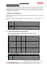
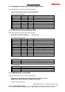
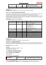
3.3 Operating Modes
Mode Description VCC pin On\Off Pin Standby
pin
Current
cons. Type.
Active
Mode
Receiver is running, doing
acquisition, tracking, position fixes
Powered High High 17mA
Power
Save
Mode
GPS receiver functions are turned
OFF, MCU in idle mode, MCU clock
is running, RTC is running
Powered
Low (or thru
NMEA
command)
High 2.2mA
Stand-
by
Mode
GPS receiver functions are turned
OFF, MCU clock is stopped, RTC is
running on the Back-up supply
No power low low
300 A
Power
Down
Mode
GPS receiver functions are turned
OFF, MCU clock is stopped, RTC is
running on the Back-up supply
No power low low
1 A