


GPS Receiver Board GPS-24 / 24A Operating Manual
Rikaline
Specifications subject to change without prior notice
Rikaline International Corp. 10F, 64, Kang-Din Road, Taipei 108, Taiwan
Tel: ++886 2 2370 4688 Fax: ++886 2 2370 4686 E-Mail: info@rikaline.com.tw Web: www.rikaline.com.tw
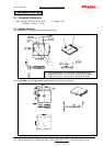
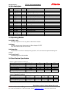
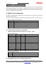
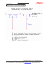
3.2 Pin Definition
PIN NAME TYPE DESCRIPTION Remarks
1 GPIO(4) I \ O GPS Status
2 NC (MODE) NU Reserved, keep float
3 NMEA Tx I \ O NMEA Serial Data Output
4 NMEA Rx I \ O NMEA Serial Data Input
5 NC (WAKE UP) NU Reserved, keep float
6 Reset I Low Active, keep float if not use *1 Will not effect hot, or cold start
7 VBAT I Backup Battery Input (1.2~2V)
8 GND PWR Ground
9 VCC PWR +3.0~3.6V DC Power Input
10 GPIO(0) I \ O SW dependent functions
A1 RF GND ANT Antenna ground
A2 RF IN ANT Antenna +
A3 RF GND ANT Antenna ground
D1 DSUMUX I Serial / DSU select
D2 DSUEN I DSU enable
D3 DSUBRE I DSU break enable
D4 DSUTX O DSU transmitter
D5 DSURX I DSU receiver
D6 DSUACT O DSU active
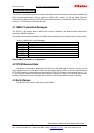
3.3 Operating Modes
3.3.1 GPIO(1) & (4)
It design as spare I\O. You may leave it disconnect of desire.
3.3.2 Reset:
It always requires reset when power-up. Max voltage is 2.0VDC
And will not effect cold start or hot start.
3.3.3 Debug Pins
All pins from D1 to D6 is for development purposes, not for end users except downloading new
software.
3.3.4 Developing Kit
Available at part no. GPS-24-SDK
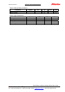
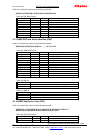
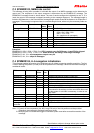
3.4 Other Electrical Specification
Table 3-1 Absolute Maximum Ratings
Parameter Symbol Min Max Units
Power Supply Voltage VDD -0.3 3.6 V
Input Pin Voltage VIN -0.3 3.3 V
Output Pin Voltage VOUT -0.3 3 V
Reset Pin Voltage Vreset -0.3 2.0 V
Storage Temperature TSTG -40 100 °C
Back-up Voltage BAT 2.2 V
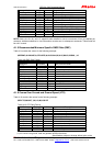
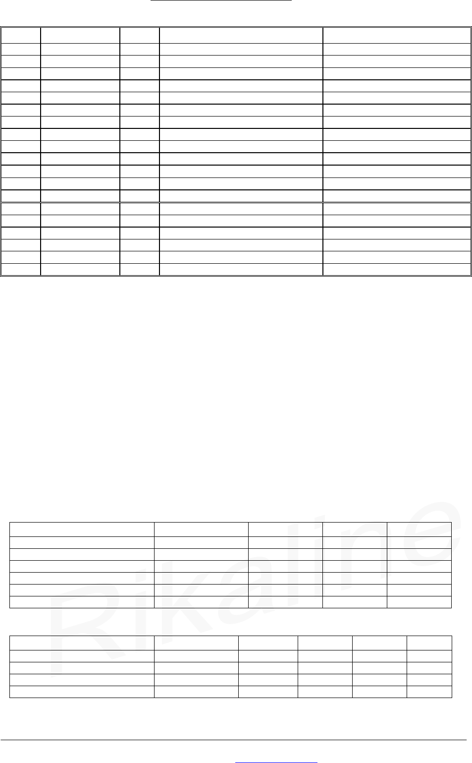
Table 3-2 Operating Conditions
Parameter Symbol Min Typ Max Units
Power Supply Voltage VCC 3 3.3 3.6 V
Input Pin Voltage VIN 2.7 3 3.3 V
Operating Temperature TOPR -40 85 °C
Operating Current ZX4120 ICC 27 mA