


GPS Receiver Board GPS-24 / 24A Operating Manual
Rikaline
Specifications subject to change without prior notice
Rikaline International Corp. 10F, 64, Kang-Din Road, Taipei 108, Taiwan
Tel: ++886 2 2370 4688 Fax: ++886 2 2370 4686 E-Mail: info@rikaline.com.tw Web: www.rikaline.com.tw
Appendix C Developer’s Setting
For all $PNMRX messages, it is possible to configure an alternative string to replace the NMRX part,
the node always responds to the $PNMRX strings and can be configured to generate and respond to
the alternative string.
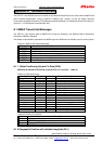
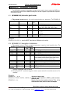
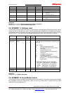
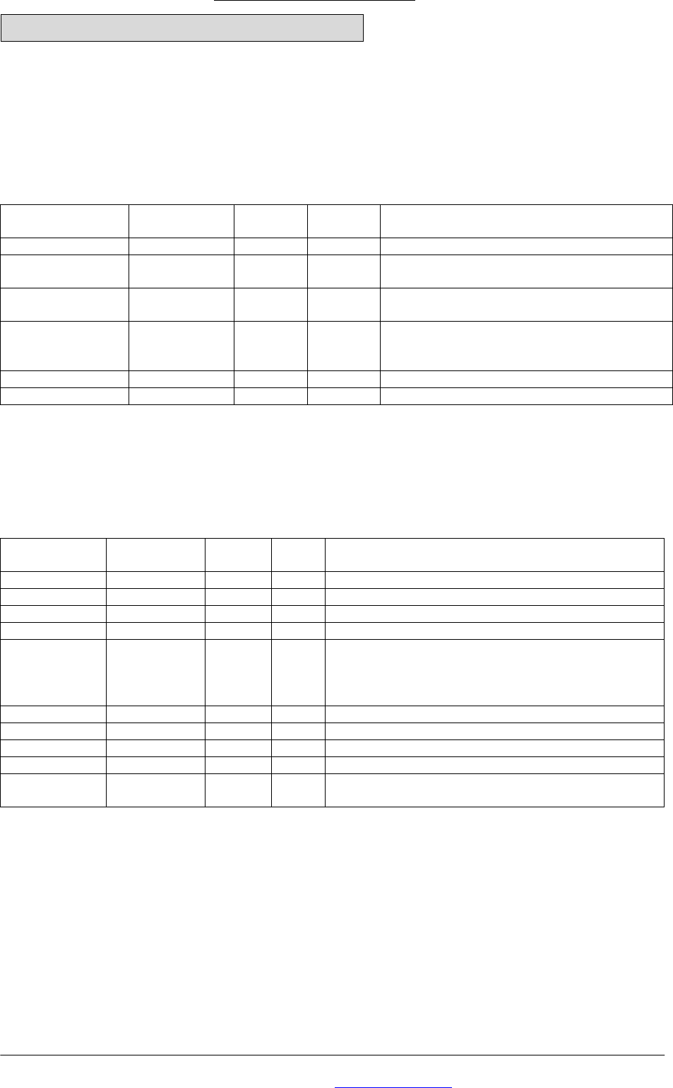
C.1 $PNMRX100, Set serial port mode
This message is sent to control the serial communications port parameters. The $PNMRX100
message format is shown below.
Field Format Min chars Max
chars
Notes
Message ID $PNMRX100 6 6 PNMRX100 protocol header.
Protocol Char 1 1 0 NMEA mode
1 NemeriX Binary Mode (under dev)
Baud Int 4 6 1200 / 2400 / 4800 / 9600 / 19200 / 38400 /
57600.
Parity Char 1 1 0. None.
1. Odd.
2. Even.
Checksum *xx (0) 3 3 2 digits.
Message terminator <CR> <LF> 2 2 ASCII 13, ASCII 10.
Examples:
$PNMRX100,0,4800,0*xx: sets the UART baud rate to 4800 bps and no parity.
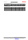
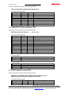
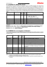
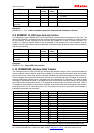
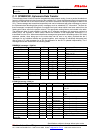
C.2 $PNMRX101, Navigation Initialization
This message is sent to initialize navigation parameters to speed up initial acquisition time. The
$PNMRX101 message format is shown below.
Field Format Min
chars
Max
chars
Notes
Message ID $PNMRX101 6 8 PNMRX101 protocol header.
ECEF_X Int (-)7 (-)7 Signed ECEF x co-ordinate in meters
ECEF_Y Int (-)7 (-)7 Signed ECEF y co-ordinate in meters
ECEF_Z Int (-)7 (-)7 Signed ECEF z co-ordinate in meters
Clock offset Int (0) 1 6 Clock offset of GPS receiver, in [Hz x 100] wrt L1.
This changes the clock bias stored in the settings
not the actual clock bias used by the system. A cold
start is necessary, in order to use this value.
Time of week Int 1 6 Offset from start of week in seconds
Week number Int 1 4 GPS week number
Channel count Int 1 2 Maximum number of TM to be used. Min 12, max 16.
Checksum *xx (0) 3 3 2 digits.
Message
terminator
<CR> <LF> 2 2 ASCII 13, ASCII 10.
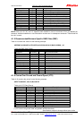
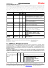
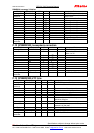
Note: 1// If used, all three X,Y, and Z components of the ECEF position must be provided, otherwise the
message is declared invalid as a whole
2// Modifying the ECEF coordinates triggers a software system reset after successful execution of the
message
Examples:
$PNMRX101,,,,,,,,8,*xx: Executes a factory reset
$PNMRX101,-742507,-5462738, 3196706,*xx: Sets the receiver position to ECEF (,) and executes a
software reset
$PNMRX101, 4,*xx: Sets the fix procedure mode the cold start. This will be
valid after each reset, until this value is changed.