


ASSEMBLY
RC456 02/11 Assembly Section 3-4
© 2011 Alamo Group Inc.
ASSEMBLY
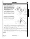
8. Two hydraulic hoses, 1/4” x 188" and one 1/4” x 192" are included. Connect the longer hose to the rear
port of the cylinder using a 90
0
elbow. Connect the shorter hose to the front port using a 90
0
elbow. Route
the hoses through the hose holder on the tongue. Install the restrictor swivel on the male end of one hose.
When the cylinder is replaced or reinstalled, the ports must go to the left side of the carrier when facing
forward.
Important: Do not operate without restrictor installed.
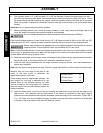
9. Before installing hydraulic lines, check for foreign material in lines. Keep hoses and fittings clean at all
times. Be sure all connections are properly sealed to avoid leakage.
Do not exceed manufacturers maximum hydraulic system pressure at 2500 psi.
If the optional tongue extension is used, install the two 1/4” x 48" hoses included in the kit on the 188" and 192"
hoses using the 1/2” NPT couplers provided. Install the restrictor fitting on the end of one extension hose.
Always wear protective eye goggles and use a magnifying glass or hold a piece of wood on
suspected leaks. Pinhole hydraulic leaks can penetrate skin. Do not touch.
Note: If fluid penetrates the skin, it must be surgically removed within a few hours by a doctor familiar with the
form of injury or gangrene may result. Make sure the weight of the machine has been taken off the hydraulic
cylinder before disconnecting hydraulic hoses.
10. Install the hose holder on the tongue center just forward of the cylinder using a capscrew and lockwasher.
Secure the hoses on the holder with the clip, capscrew, lockwasher, and nut.
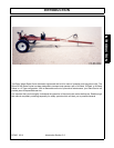
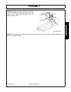
11. Install the rake mount assemblies on the wings, as shown, using two U-bolts, nuts, and lockwashers to
secure each assembly.
Note: Left and right mounting heads are used. Check for proper identification of left and right mounting heads.
Measure from the front edge of the wing to the
center of the rake mount to determine the
approximate location of the rake.
These settings are only approximate settings. The
final position on the wing is determined by the
desired width of the windrow. Moving the rake
mounts forward on the wing makes the windrow
wider. Moving the rake mounts rearward makes the
windrow narrower.
12. Install the wheel rakes on the mount tube by inserting the rakes main frame tube into the tubes on the
rake mounts. This operation can be made easier if the carrier is connected to the tractor tongue,
hydraulics are connected and the wings are extended. Install the clamps on the rake tubes. Tighten the 1/
2” x 1 1/2” bolts, nuts, and lockwashers snugly. The ears at the top of the clamp should be on either side
of the tab on the mount tube so the rake can “float” as it works.
4 Wheel Rakes 35”
5 Wheel Rakes 25”
6 Wheel Rakes 13”