


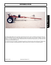


ASSEMBLY
RC456 02/11 Assembly Section 3-3
© 2011 Alamo Group Inc.
ASSEMBLY
ASSEMBLY INSTRUCTIONS
1. Layout and identify all parts. Many parts will be
partially assembled by the manufacturer. The
main frame and swing arms are already
assembled, along with the tension spring and
adjustment chains, and the hydraulic cylinder
is installed by the manufacturer. The spindles
and hubs are also installed on the axle.
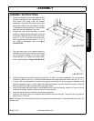
2. Support the main frame assembly on sturdy
stands and install the axle assembly under the
main frame. Measure from the rear of the main
frame 17" to 18" to the back side of the axle
tube. Secure the axle with three 4" x 5 1\2” x
5\8” U-Bolts, lockwashers, and nuts. Figure
Asm-RK-0160
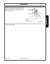
3. The axle may need to be moved forward or
backward until the caster wheels on the wings
roll in the proper location on the axle ramps
(See Illustration 2). Tighten the U-Bolts when
axle is properly located. Figure Asm-RK-0161
4. Install the tongue on the main frame using three 5/8” x 2" bolts, nuts, and lockwashers. On some models,
a reinforcing plate is used. If so, install the plate beneath the tongue and main frame using six 1/2” x 1 1/
2” bolts, nuts, and lockwashers. Install a hose support on the top bolt as the tongue is installed. If the
optional extended tongue is used, install the extension between the main frame and tongue using the
bolts provided and install a second reinforcing plate if used.
5. Install the threaded rod hose holder in the threaded hole on top of the tongue. Install a 1/2” jam nut on the
rod before installing. Tighten the jam nut after the rod is position.
6. Install the support jack on the tongue using the pin supplied.
7. Install the tire on the wheel rims supplied and install the rims on the hubs. Torque the four lug bolts on
each wheel to 75 Ft-Lbs.
Note: The height of the tires used will effect the operation of the wheel rakes. It is recommended that 195 x 14"
tires be used.