


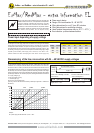
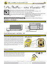

Power supply design
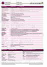
Rated current in acc. with motor running time
Voltage Current 3/7,5s 15s 30s 60s 120s
230 V I
rated 0,5 A 0,3 A 0,15 A 0,10 A 0,10 A
120 V I
rated 0,75 A 0,4 A 0,3 A 0,25 A 0,25 A
48 V I
rated 2,0 A 0,5 A 0,3 A 0,2 A 0,2 A
24 V I
rated 4,7 A 1,45 A 0,52 A 0,4 A 0,4 A
The design of the on-site supply, depends on the selected motor running time and selected
supply voltage. Accompanying values are "about values", since there can be construction
unit dispersions within electronics. The power consumption in the blocking position is run
time independently with max. 20 W. The power consumption for the heater is approx. 16W.
The heading is running only if the motor is in idle position! The initial starting supply voltage
required by the actuators power supply unit is around 2,0 A for about 1 Sec.
(Please consider this while concepting the cross section ot the supply line)
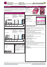
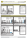
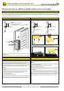
Dimensioning/Design of the supply line
On long distances between voltage supply and drive, voltage drops occur due to line
resistances. As a consequence with 24 VAC/DC the actuator receives a too low tension
and does not start. In order to prevent this, the cross section of the inlet line is to be
designed/dimensioned accordingly. The accompanying formula allows the calculation of
the necessary line cross section, perhabs provides the maximally permitted conduit length
utilizing the existing line cross section. Alternatively the secondary voltage can be increased
by selecting a transformer. For calcualtion purposses, following characteristics are essential:
UV = supply voltage in [V]
A = line cross section in [mm²]
L = conduit length in [m]
Factor 0.0714 = drive-specific factor
[Vmm²/m] ( based on the electrical conductivity of electrolytic copper with a coefficient of
56m/Wmm²)
pannel
length "L" [m]
terminal box actuator
line cross section "A" [mm²]
voltage
"Uv" [V]
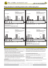
Formula for max. cable length "L" at cable
cross section "A"
L = A
l
(Uv-18V) : 0,0714
Formula of needed cable cross section
"A" at a cable length of "L"
A = 0,0714
l
L : (Uv-18V)
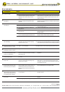
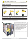
The "EL"-data sheet contains additional information for ExMax and
RedMax actuators of the size "S", for the optimization and simplification
in regard to planning, installation and initial startup. It provides
influences of external factors in reference to the safe initiation of
the actuators, as well as technical references and problem solutions
(error indication). With the error indication, functions can be examined
and different error/problems can be adjusted locally.
Example: A = 1,5 mm², Uv = 24 V
Lengthof cable L = 126 m
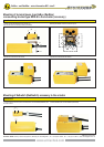
Example: L = 250 m, Uv = 30 V
Cross section of A = 1,5 mm²
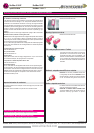
Example:
24 V power supply with wire diameter 1,5 mm² = 126 m
Uv [V]
Schischek GmbH Germany D-90579 Langenzenn, Mühlsteig 45, Gewerbegebiet V, Tel. ++49 (0)9101-90810, Fax ++49 (0)9101-908177, Email ExMax@schischek.de
ExMax-.. and RedMax-.. extra information EL - size S
EXPLOSIONPROOF
u Power supply design
u Design of line cross section 24...48 VAC/DC
u Wiring alternatives for on-off, 3-pos, BF actuators
u Wiring alternatives for modulating actuators
u Use at ambient temperatures down to -20°C / - 40°C ( )
u
Error indication - problem treatment/solution
Power input depending of supply voltage
Dimensioning of the line cross section with 24 ....48 VAC/DC supply voltages
ExMax/RedMax - extra information EL
For additional mechanical data have a look at "extra information ME"
28
27
26
25
24
23
22
21
20
50 100 150 200 250 300 350 400
L[m]
1 mm² 1,5 mm² 2,5 mm²
4 mm²
www.schischek.com