


www.schischek.com
Technical data RedMax-5.10-BF RedMax-15-BF
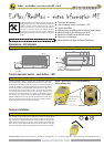
Accessories or special solutions - size S
Schischek GmbH Germany D-90579 Langenzenn, Mühlsteig 45, Gewerbegebiet V, Tel. ++49 (0)9101-90810, Fax ++49 (0)9101-908177, Email ExMax@schischek.de
RedMax-5.10-BF RedMax-15-BF
Special makes RedMax-..-VA/-CT
EXPLOSIONPROOF
Certification PTP 04 ATEX 2106
ATEX Directive 94/9/EG (ATEX)
Approval for gas II3G EEx nC II T6 II3(1)G EEx [ia] IIC gas, mist, vapour,
zone 2
Approval for dust II3D IP66 T80°C dust, zone 22
Identification CE Nr. 0158
EMC EMC-directive 89/336/EG
Low voltage Low-voltage directive 72/23/EG
IP-Protection IP 66
Potential compensation external PA-terminal, 4 mm²
EEx-i circuit data see table below wiring diagrams
Torque motor 5 / 10 Nm selectable on site 15 Nm
Torque spring return (F) min. 10 Nm min. 15 Nm
Dimension of external torque above mentioned torques are min. torques in blocked position, eternal torque should be max. 80% of max. actuator torque but min. 3 Nm
Supply voltage/Frequency 24...230 VAC/DC, + 15 % / - 20% , self adaptable, Frequency 50...60 Hz +/- 20 %
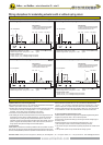
Dimension max. starting currents see table (in acc. with voltage, I
start >> I rated), max. 20 W blocking position, approx. 16 W for heater
Protection class class I (grounded)
Angle of rotation and indication 95°, incl. ~ 5° pre-tention, mechanical value indication
Working direction selectable by left/right mounting to the damper/valve shaft
Motor running time 3 / 15 / 30 / 60 / 120 sec. at 90° selectable on site
3 sec. mode - motor In acc. with the supply voltage rand external torque 3 to 4 sec at 90° angle of rotation
Motor brushless DC Motor
Spring return (F) spring return in the event of loss of power
Spring return running time (F) spring return in 3 sec., or 10 sec. at 90°, selectable on site
3 sec. mode - spring return in acc. with external torque 3 to 4 sec. at 90° angle of rotation
Safety operations at 10 sec (F) min. 10.000 in acc. with construction of damper and ambient
Safety operations at 3 sec (F) min. 1.000 in acc. with construction of damper and ambient
Response time spring return up to 1 sec. after power failure
Control mode On-off and 3-pos in acc. with wiring, selectable on site
Intrinsic safe circuit Additional EEx-i circuit to connect a passive potential free thermostat as a safety sensor, e.g. type FireSafe
Integratet aux. switches 2 aux. switches, switching at 5° and 85° Angle of rotation
Axle of the actuator double squared 12 x 12 mm, direct coupling, 100 % overload protected and 100 % self locking up to 15 Nm
Electrical connection cable, ~1 m, diameter of wires 0,5 mm² for connection inside hazardous areas an terminal box is required!
Diameter of cable ~ Æ 9,6 mm + ~ Æ 6,2 mm
Cable gland M16 x 1,5 standard - cable - and wire entries are integral part of explosions proof encapsulation; tested acc. to EN 50018
Manual override Use Manual override only if supply voltage is cut, use delivered socket wrench, slow motion, enough torque/force is required
Attention: with manual operation of the spring danger of injury exists, with release/let go the hexagonal spanner!
Integral heater integral heater, controlled, for ambient temperature down to - 40°C
Housing material Aluminium die cast housing, painted (optional in stainless steel version AISI 316 - type RedMax-...-VA, amercoat painting type RedMax ...-CT)
Dimensions l x w x h 210 x 95 x 80 mm, for diagramm see extra information ME
Weight ~ 3,5 Kg Aluminium housing (stainless steel ~ 7 Kg)
Ambients storage temp. - 40..+ 70°C, working temperature - 40..+ 40°C at T6 and - 40...+ 50°C at T5, humidity in acc. with EN 60335-1
Operation mode at
runningtime motor 3 sec at 3 sec. 10 % ED, max. 1 on-off cycle per minute (must be guaranteed by control system)
Operation mode ex
runningtime motor 15 sec at 15/30/60/120 sec. 100 % ED
Self adjustment if you select 3 sec. and 15 sec. mode for motor you need to start the self adjustment mode
Maintenance maintenance free, maintenance must be complied with regional standards, rules and regulations
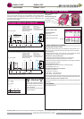
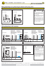
Wiring diagrams (SB) SB 7.0 / 7.1 SB 7.0 / 7.1
Delivery 1 actuator, 1 m cable, double squared shaft connection 12x12 mm, 4 screws M 4 x 100, 4 nuts M 4
socket wrench for simple manual override
Parameter at delivery 5 Nm, 30 sec./90° 15 Nm, 30 sec./90°
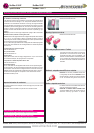
Explosion proof RedMax actuators - size S
RedMax-..-VAabove listed types in stainless steel version, housing AISI 316.
RedMax-..-CTabove listed types in Al-housing with amercoat painting, parts nickel-plated
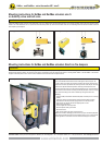
RedBox-... Terminal box for zone 2, 22.
MKK-S mounting bracket for EEx-e terminal boxes type RedBox-... direct on actuator
RedSwitch 2 external aux. switches, 2 x EPU, adjustable, for zone 2, 22
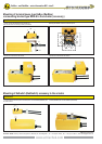
KB-S clutch for damper shafts Æ 10...20 mm and
10...16 mm.
HV-S comfortable manual override for RedMax actuators size S
Adaptations various adaptations for dampers/valves on request
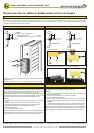
BFH-S Mounting holder for actuators at fire danger area
FireSafe Sensor with manufacturer certificate in acc. with ATEX.
AR-12-xx Reduction of square damper connection from 12 mm to 11, 10, 9, 8