


128-7829A
9 of 12
Page 9
To test this circuit, while the vehicle is running under control of the remote start unit, open
the vehicle’s hood. The remote start unit should shut down immediately. If not, check the
wiring to the control module and the under hood pin switch. DO NOT RELEASE THE
VEHICLE TO THE CONSUMER IF THIS CIRCUIT DOES NOT PERFORM AS SPECI-
FIED.
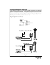
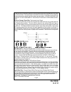
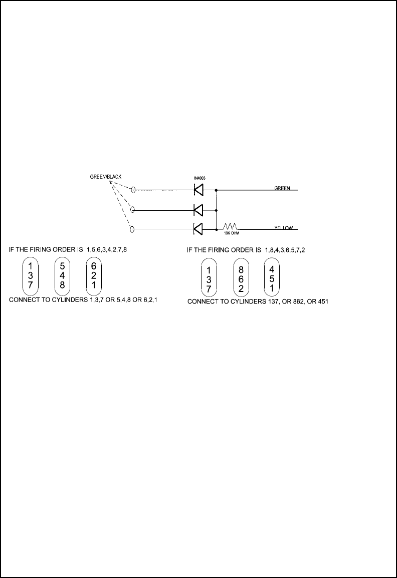
Green w/ Orange Trace Wire: Tachometer Input Signal
This wire will continually monitor the engine's tach rate while the unit is under power of
the Remote Start module. This wire will be routed to the vehicle ECM tach input or
through the firewall into the engine compartment and connect to the negative side of the
ignition coil. This Remote Start unit learns the tach rate of the vehicle and in most cases
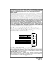
will operate properly from one multi coil pack regardless of the number of cylinders. If
the vehicle has a single coil unit for each cylinder, it may be necessary to connect this
wire to more than one cylinder for proper tach reference. See multi coil wiring detail
below.
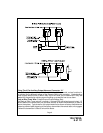
Dark Blue Wire: Delayed 250mA Pulsed Channel 3 Output
The Dark Blue wire supplies a 250mA ground pulsed output whenever channel three
of the receiver is accessed. Pressing the pre-programmed transmitter button for
three seconds will access channel two. This is a low current output and must be
connected to a relay to supply power to the trunk release or the circuit you wish to
control. Connect the Dark Blue wire to terminal # 86 of a VF45F11 P&B relay or
equivalent. Connect terminal # 85 of the relay to a fused + 12 volt source. Connect
the common, normally open, and normally closed contacts of the relay to perform the
selected function of channel 3.
Black w/ White Trace Wire : 250 mA Horn Output
The black w/ white trace wire is provided to beep the vehicle’s horn. This is a transistor-
ized low current output, and should only be connected to the low current ground output
from the vehicle’s horn switch. If the vehicle uses a + 12 VDC horn switch, then con-
nect the black w/ white trace wire to terminal 86 of the AS 9256 relay ( or an equivalent
30 Amp automotive relay ),and connect relay terminal 85 to a fused
+ 12 VDC battery source. Connect relay terminal 87 to the vehicle’s horn switch output,
and connect relay terminal 30 to a fused + 12 VDC battery source.
Light Blue Wire: Ground Output While Running Under Remote Start Control
This wire provides a 300mA ground output that becomes active 3 seconds before the
Remote Start Unit initializes and remains grounded while running plus an additional 4
seconds after the Remote Start Unit turns off. In all of the applications described
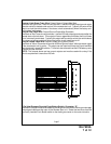
Setting Up The System Programming Features:
Bank 1 Transmitter Channels