


128-7829A
3 of 12
Page 3
DO NOT PLUG THE SIX PIN MAIN POWER HARNESS OR THE MULTI PIN INPUT /
OUTPUT HARNESS INTO THE CONTROL MODULE UNTIL ALL CONNECTIONS TO
THE VEHICLE HAVE BEEN MADE. AFTER SELECTING YOUR TARGET WIRES AS
DEFINED BELOW, DISCONNECT THE NEGATIVE BATTERY CABLE FROM THE VE-
HICLE BATTERY PRIOR TO MAKING ANY CONNECTIONS.
Note: Do not remove the fuse holders from this wire harness.
Fuses must be used and located as close as possible to the power
source for adequate protection of the vehicle.
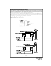
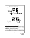
WIRING THE 6 PIN MAIN POWER HARNESS Connector “C”:
Fused RED w/ WHITE TRACE WIRE: + 12 volt Battery 1 Source
Locate the vehicle battery wire(s) at the ignition switch. Verification: These wires will register
voltage in all positions of the ignition switch. Connect the Red w/White wire to the vehicle's battery
wire. This wire provides power for the control circuit as well as the ignition 1 and ignition 2 relays.
Fused RED WIRE: + 12 Volt Battery 2 Source
Locate the vehicle battery wire(s) at the ignition switch. Verification: These wires will register
voltage in all positions of the ignition switch. Connect the Red wire to the vehicle's battery wire.
This wire provides power for the start relay and the accessory relay.
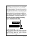
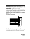
the remote start unit. If the vehicle is being worked on, this hood switch prevents the
remote start activation even if the RF command to start is issued. This switch must be
installed in all applications. Failure to do so may result in personal injury or
property damage.
Mount the switch in the hood locations away from water drain paths. If necessary, the
included bracket may be used to move the switch away from rain gutters or allow mount-
ing to the firewall behind the hood seal. In both cases the switch must be set up to allow
the hood to depress the switch at least 1/4 inch when the hood is closed and fully extended
when the hood is opened. For direct mounting, a 1/4 inch hole must be drilled. Carefully
check behind the chosen location to insure the drill will not penetrate any existing factory
wiring or fluid lines.
Drill a 1/4" hole in the desired location and thread the pin switch into it using a 7/16" nut
driver or deep well socket. If using the mounting bracket, first secure the bracket to the
desired location and secure the pin switch in the pre-threaded mounting bracket hole.