


128-7829A
2 of 12
Page 2
INSTALLATION OF THE MAJOR COMPONENTS:
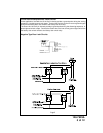
CONTROL MODULE:
Select a mounting location inside the passenger compartment (up behind the dashboard).
The mounting location selected must be within 24" of the ignition switch wiring harness to
allow connection of the 6 pin main wiring harness.
Be certain that the chosen location will not interfere with proper operation of the vehicle.
Avoid mounting the module to or routing the wiring around the steering shaft/column, as
the module or wiring may wrap around or block the steering wheel preventing proper
control of the vehicle. Secure the module in the chosen location using cable ties or
screws as necessary.
Do Not Mount The Module In The Engine Compartment, as it is not waterproof.
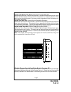
DASH MOUNTED LED:
The small LED included in the kit will serve as a visual indicator of the system’s status
and provide a visual deterrent to a potential thief. The LED also provides important feed
back information during the transmitter and feature program modes. The LED should be
installed in the dash in an area highly visible so that it may be seen from the driver's seat
as well as from outside the vehicle. Inspect behind the chosen location to insure that the
drill will not penetrate any existing factory wiring or fluid lines. Carefully drill a 1/4" hole in
the desired location and pass the connector end of the LED through the hole and toward
the control module. Press the LED firmly into place until it is fully seated in the mounting
hole.
THE RECEIVER/ANTENNA ASSEMBLY:
The Superregenerative Receiver Antenna Assembly provided with this unit allows routing
from below the dash board for maximum operating range. Choose a location above the
belt line (dashboard) of the vehicle for best reception. Special considerations must be
made for windshield glass as some newer vehicles utilize a metallic shielded window
glass that will inhibit or restrict RF reception. In these vehicles, route the antenna toward
a rear window location for best reception. Secure the antenna with double stick tape
provided. After securing the antenna with tape, we advise also securing a section of the
antenna cable to a fixed support. This will prevent the antenna from dropping down in
case the double stick tape is exposed to extreme heat which may loosen it's gummed
surface. Route the connector toward the control module using caution not to pinch the
cable as this will cause poor or no RF reception to the control module.
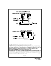
VALET/PROGRAM/MANUAL OVERRIDE SWITCH :
Select a mounting location that is easily accessible to the operator of the vehicle. It is not
necessary to conceal the switch. However, concealment is recommended as it offers a
higher level of security. The switch can be mounted to the lower dash panel in the driver's
area. Inspect behind the chosen location to insure that adequate clearance is allowed for
the body of the switch, and also that the drill will not penetrate any existing factory wiring
or fluid lines. Drill a 9/32" hole in the desired location and mount the switch by passing it
through the panel from the underside. Secure the switch using the nut, star washer.
Route the switch's connector toward the control module.
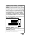
NOTE: During the program sequence, there are times when this switch and the ignition
switch will be used simultaneously. We recommend that the pushbutton switch be mounted
on the left side of the ignition switch to facilitate this operation.
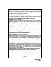
HOOD PIN SWITCH:
The pin switch included in this package are intended for protecting the hood area of the
vehicle. In all cases, the switch must be mounted to a grounded metal surface. When
the pin switch is activated, (hood/trunk open), it will supply a ground to the input wire
activating the alarm. In addition, the hood switch is required for the safety shut down of