27
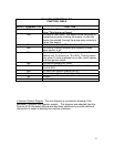
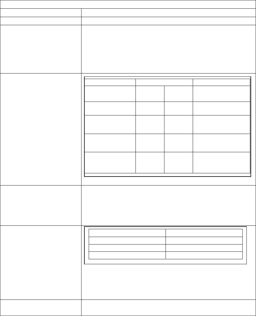
The following table provides a quick reference for verifying the measurement
values for each L-Jetronic fuel injection component.
Quick Reference Table - Fuel Injection Component Values
Fuel Injector Valves 2 – 3 ohm coil resistance
Thermo-time Switch Below 95
0
F = 0 ohms Above 95
0
F = Infinite
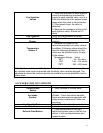
Cold Start Valve Remove cold start valve from manifold and place in a
container to collect the fuel, reconnect electrical plug.
Disconnect plug from thermo-time switch and apply
12Vdc to pin W and ground to pin G of the connector.
Pressurize the fuel system and observe fuel exiting the
cold start valve.
Air Flow Sensor
Auxiliary Air Regulator Pins of Aux Air Reg should read 30 Ω. Alternate check
of contacts would be to read from 88c of dual relay
and pin 35 of ECU plug. Aux Air Reg should be open
when cold. Apply 12 Vdc to pins and it should close
completely.
Temperature Sensor II
(Troubleshooting Hint – Disconnect the sender unit wire at the
disconnect near the distributor and substitute with resistors at specific
values (2.5K Ω when temp is 70
0
F) and see if problem goes away.
Ground one side of resistor to engine block.)
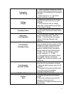
Throttle Valve Switch Pins 18 to 3 - 0 Ω with throttle valve wide open
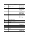
Function Terminal Contacts Measurements
Air Flow
Sensor
ECU
Plug
Infinite = ∞
Ohms = Ω
Air Flow plus
limiting resistor
6 to 9 6 to 9
200 – 400 Ω
Air Flow without
limiting resistor
7 to 8 8 to 7
120 –200 Ω
Temperature
Sensor in AFS
6 to 27 6 to 27
2k Ω at room temp
Fuel Pump
Contacts
36 to 39 N/A
∞ with AFS flap
closed, 0 Ω with
AFS flap open
Value Temperature Range
2k – 3k Ω
68
0
F
7.5k – 12k Ω
14
0
F
250 – 400 Ω
176
0
F


