


23
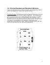
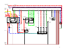
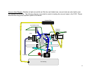
The following diagrams of connector plugs are provided to assist in the isolation
of fuel injection component failures. Specific characteristics of the connector
plugs and reference pins have been identified in order to aid the 912E owner in
taking voltage and resistance measurements. It is most often easier to isolate
the fuel injection problem by using an access point such as a related connector
plug on another component than by attempting to remove the connector on the
suspect fuel injection component, and then trying to take measurements on the
component itself.
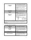
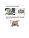
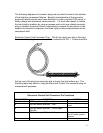
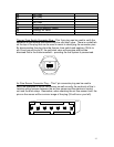
Electronic Control Unit Connector Plug – This 35 pin plug has a tab on the right
hand side of the plug that can be used as a reference for Pin 1. Please note that
the top row of the plug has more pins and is longer than the bottom row. The
following table may assist in using the Electronic Control Unit connector plug for
measurement purposes.
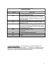
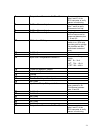
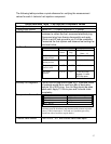
Electronic Control Unit Connector Pin Functions
PIN NUMBER FUNCTION NOTES
1
RPM input from ignition coil
2
Throttle switch position – Idle
Unsure of this pin being
used.
3
Throttle switch position – Wide Open
Throttle
4
12Vdc from pin 86 of dual relay
Source is ignition switch
pin 50, starter operate
position
5
Ground
1
19
18
35