


Pelco Manual C1925M (3/99) 9
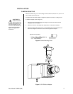
b. Adjust the lens and the CS-mount ring together until picture is sharpest.
c. Hold the lens and CS-mount ring in place and turn the back-focus locking
ring clockwise to tighten.
Motorized Zoom Lenses
1. With the camera operating, position the camera to view an object at a distance not
less than 45 feet (15 meters) away.
2. Using the camera controller, set the lens in the following manner:
a. Zoom out as far as possible (zoom wide).
b. Focus on the distant object (focus far).
c. Open the iris as wide as possible (iris open). Use a neutral density filter with
auto-iris lenses in outdoor or bright light settings to ensure maximum iris opening
during back-focus adjustment. When a neutral density filter is not available, point
the camera to a relatively dark area to obtain the greatest iris opening.
3. Adjust back-focus until the object is in sharpest focus.
a. Turn the back-focus locking ring counterclockwise to loosen the CS-mount ring.
b. Adjust the lens and the CS-mount ring together until picture is sharpest.
c. Hold the lens and CS-mount ring in place and turn the back-focus locking ring
clockwise to tighten.
4. Zoom in all the way on the distant object, then focus the lens for best picture.
5. Zoom out all the way while observing the focus on the monitor (known as “tracking”). If
the image stays in focus throughout the entire zoom range, the back-focus is correct.
Otherwise repeat the process beginning with step 1.
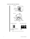
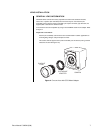
CAMERA SYNCHRONIZATION AND V-PHASE
When using a DC power supply, synchronization is internally locked and V-phase control is
inoperative.
V-phase adjustment is unnecessary when using AC power with a single camera.
When powering more than one camera with AC, phase differences may occur as a result of
being connected to different power groups. These phase differences become apparent as a
brief rolling of the picture each time cameras are switched, known as vertical roll.
Vertical roll can be corrected by synchronizing the cameras using the V-phase control
button inside the opening on the back of the camera (refer to Figure 1). Each time the
V-phase button is pressed, the line lock position shifts by 60 degrees.
The CCC4000 Series cameras generate a video signal with synchronization pulses
corresponding to the following:
CCC4000-2 NTSC Standard
CCC4000-2X PAL Standard
CCC4001-2 NTSC Standard
V-PHASE ADJUSTMENT
Generally, it is necessary to have two people in communication when cameras are
synchronized: one person at the camera to be synchronized and a person at the monitor to
observe the vertical “roll” and the effect of any adjustments made at the camera.
1. Choose a camera to which all of the other cameras will be synchronized. Go through
the available cameras and determine the best camera to which the others should be
synchronized.