


38 •Insert the passenger's handle into the hole on
the dashboard.
39 •Attach the handle with the screws provided.
40 •Snap fit the petrol cap.
41 •Insert the seat base (removed previously) on the
driver's side.
42 •Insert the battery (charged previously) into the
compartment under the seat on the passenger's
side.
43 •Thread the battery plug and the electrical system
plug through the holes in the passenger’s seat
base.
44 •Insert the seat base on the passenger side.
45 •Connect the battery and electrical system plugs.
46 •Fasten down the seat bases using 4 screws (two
on each side).
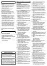
47 •Insert the two short sections of the safety belts
into the seat bases (in the holes near the gear
lever), taking care to insert all of the section of
belt highlighted in detail A. Note: the safety belt
buckle buttons must be facing the gear lever, as
shown in the figure.
48 •Unscrew the knobs from the seat base.
49 •Position the seat. Note: the seat can be adjusted
in length to two different positions, depending on
the height of the child.
50 •Screw the knobs back into position.
51 •Lower the seat.
52 •Tighten the safety screw. Repeat for the other
seat.
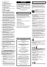
53 •Assembling the roof bars.
54 •Join parts A, B and C of the front of the roof
bars as shown in the picture, inserting the fixing
screws into the upper holes. Take care with the
orientation of the lower ends of parts B and C.
55 •Join parts A, D and E of the rear section of the
roof bars as shown in the picture, inserting the
fixing screws in the lower holes. Take care with
the orientation of the lower ends of parts D and
E.
56 •Push down to mount the roof bars on the
vehicle.
57 •Insert the clips on parts D and E of the roof
bars. Take care with the direction of insertion of
the clips.
58 •Insert the ends of the side guards into the clips.
59 •Tighten the fixing screws.
60 •Attach the roof bars at the rear with 2 screws.
61 •Attach the roof bars at the front with 2 screws.
62 •Attach the long sections of the safety belts to
the roof bars.
63 •Mount the three fog lights on the roof bars and
attach them with the screws provided (one per
light).
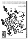
64 •Remove the protectors from the rear axle.
65 •Insert the axle into the rear of the vehicle, as
shown in the figure.
66 •Position the driver in the inside of one of the
two larger wheels.
67 •Slide the wheel onto the axle with the driver
towards the vehicle.
68 •Slide a washer onto the axle.
69 •Fasten the wheel, tightening one of the four nuts
supplied with the spanner provided.
•Repeat the fitting operations for the other rear
wheel. Important: carry out the operations while
holding the axle still on the opposite side with
the help of the second spanner provided.
70 •Remove the protectors from the front axles.
71 •Slide a washer onto the axle.
72 •Slide one of the remaining wheels (narrower
than the rear wheels) onto the axle.
73 •Slide a washer onto the axle.
74 •Fasten the wheel, tightening one of the two
remaining bolts with the spanner provided.
•Repeat the fitting operations for the front wheel
on the other side.
75 •Snap fit the four hub covers onto the wheels.
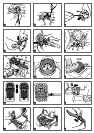
FEATURES AND USE OF THE VEHICLE
76 •RADIO - Remove the two screws as shown in
the figure to extract the radio and insert the
batteries.
77 •Use a tool to lever the upper part of the radio
front panel and extract it.
78 •Release the screw on the battery compartment
cover.
79 •Insert two AA 1.5V batteries with the polarities
as indicated. Close the battery compartment
cover. Important: always tighten the screw.
80 •Insert the antenna and the radio into the housing
on the dashboard.
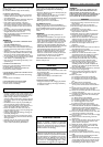
81 •Radio functions:
•A - Socket for an MP3 reader jack.
IMPORTANT!: Connect the MP3 reader (not
included) to the vehicle radio using a cable NO
longer than 150 cm.
•B - Radio station selector.
•C - On/Off buttons.
•D - Radio On indicator light.
•E - Volume control knob.
•F - Digital clock adjustment buttons.
82 •Driving cab features:
•A - Steering wheel.
•B - Fully functional radio (see fig 81).
•C - Speedometer and battery charge level panel
(see fig 83).
•D - Passenger handle.
•E - Accelerator/electrical brake pedal (see fig 84-
85-86).
•F - Gear lever (see fig 87).
•G - Drinks holder (see fig 88).
•H - MP3 player storage compartment.
83 •CONTROL PANEL - The lower part of the
control panel shows the battery charge level. The
green light indicates that the battery is charged,
orange indicates that the battery level is getting
low and a red light indicates that the battery
must be recharged. At the top of the control
panel the greed LEDs light up progressively as
the vehicle’s speed increases (they are for play
purposes only and do not indicate the true
speed of the vehicle).
84 •ACCELERATOR/ELECTRICAL BRAKE PEDAL -
When the accelerator pedal is pressed, the
vehicle starts moving. When the pedal is released,
the electrical brake is activated, automatically
stopping the vehicle.
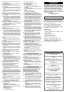
85 •The second gear lock is located on the pedal.
When the vehicle is removed from its packaging,
the second gear lock is positioned as shown in
figure A (LOW), limiting the vehicle to the lower
speed. When the second gear lock is positioned
as shown in figure B (HIGH), the vehicle can
travel at the faster speed.
86 •To adjust the second gear lock to position B
(HIGH), release the second gear lock fixing
screw and move the unit upwards. Important:
always replace the fixing screw.
87 •GEAR LEVER - When the gear lever is in the
vertical position, the vehicle travels forward at
LOW or HIGH speed. When the gear lever is
pulled back and the accelerator pedal is pressed
at the same time, the vehicle travels in reverse.
88 •DRINKS HOLDER - There are two drinks
holders for cans or bottles.
89 •REAR BOX and SUSPENSION - The rear of the
vehicle has a spacious cargo box and real
functional suspension on the wheels.
90 •SAFETY BELT - To fasten the safety belt, insert
the end of the longer belt section into the buckle
on the shorter belt section, pushing the two
parts together.
91 •To release the safety belt, press the buckle
button and at the same time separate the two
elements.
92 •To change the length of the safety belt, move the
adjuster as shown in the figure.
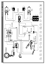
REPLACING THE BATTERY
93 •Release the passenger seat safety screw and lift
the seat.
94 •Unscrew the knobs and remove the seat.
95 •Unscrew the two seat base screws. Disconnect
the battery and electrical system plugs.
96 •Extract the seat base and pull out the plugs.
97 •Replace the battery.
•Replace the seat base after passing the plugs
through the holes. Connect the plugs and replace
the seat.
98 •WARNING: always replace and tighten all the
knobs and screws.
CHARGING THE BATTERY
WARNING: BATTERY CHARGING AND ANY
OTHER WORK ON THE ELECTRICAL SYSTEM
MUST BE CARRIED OUT BY ADULTS.
THE BATTERY CAN ALSO BE CHARGED
WITHOUT REMOVING IT FROM THE TOY.
99 • Disconnect the electrical system plug A from
the battery plug B, pushing on the sides of the
plugs to release them.
100 • Plug the battery charger into a domestic power
outlet following the instructions enclosed with
it. Connect plug B to the battery charger plug
C.
101 • When charging is complete, disconnect the
battery charger from the domestic power
supply and then disconnect plug C from plug B.
102 • Fully insert plug B into plug A until it clicks into
position.
• WARNING: when the charging operations are
complete, always replace and tighten all the
knobs and screws.
103 • The battery can also be charged outside the
vehicle. This means that if you have a spare
battery, the child can continue to use the toy.
Lisez attentivement ce manuel d’instructions pour
vous familiariser avec le modèle et apprendre à votre
enfant à le conduire de façon correcte, amusante et
en toute sécurité. Conserver ensuite ce manuel pour
pouvoir vous y référer à l’avenir.
Avant d’utiliser le véhicule pour la première fois,
mettez en charge la batterie pendant 18 heures.
Ne pas appliquer cette règle pourrait être à l’origine
de dommages irréversibles à la batterie.
• Âge 3 - 10 ans
• Véhicule à 2 places
• 1 Batterie rechargeable de 24 V 15 Ah scellée au plomb
• 2 roues motrices
• 2 moteurs de 280 W
• Vitesse en première 5 km/h
• Vitesse en seconde 10,5 km/h
• Vitesse en marche arrière 5 km/h
Peg Perego se réserve le droit d’apporter, à tout
moment, des modifications aux modèles et aux
données figurant dans ce livret, pour des raisons de
caractère technique ou de management.
PEG PEREGO® vous remercie d’avoir choisi ce
produit. Depuis plus de 50 ans, PEG PEREGO
accompagne les promenades des enfants. Dès leur
naissance, avec les landaus puis avec les poussettes et
plus tard, avec les jouets à pédales et à batterie.
Découvrez sur notre site la gamme complète des
produits, les nouveautés et d’autres renseignements
sur le monde Peg Perego.
www.pegperego.com
DENOMINATION DU PRODUIT
Polaris Ranger RZR
CODE D’IDENTIFICATION DU PRODUIT
IGOD0513
REFERENCES NORMATIVES (origine)
Directive générale Sécurité des Jouets 88/378/CE
Standard EN 71 / 1 -2 -3
Standard EN62115
Directive Compatibilité électromagnétique (CEM)
2004/108/CE
Standard EN55022 - EN55014
Directive européenne RAEE 03/108/CE
Directive européenne RoHS 2002/95/CE
Directive Ftalati 2005/84/CE
Norme EN 60825-1
Ce produit n’est pas conforme aux normes de
circulation routière et, par conséquent, ne doit pas
circuler sur les voies publiques.
DECLARATION DE CONFORMITE
PegPerego S.p.A. déclare sous son entière
responsabilité que l’article ci-dessus référencé a
été soumis à des essais internes et a été
homologué auprès de laboratoires externes et
indépendants, conformément aux normes en
vigueur.
DATE ET LIEU DE DELIVRANCE
Italie - 06.05.2008
Peg Perego S.p.A. Via A. De Gasperi, 50
20043 Arcore (MI) - ITALIA
FRANÇAIS
DECLARATION DE CONFORMITE
RECOMMANDATIONS IMPORTANTES