


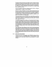
FTB500
Series of meters establish a linear
response after an initial offset correction when operating at a constant
viscosity.
3
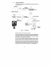
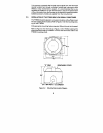
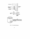
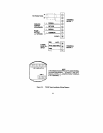
FTBSOO
flowmeter are shown
in Figures l-2 and 1-3. The
pelton
rotor causing it to
rotate The motion of the rotor is sensed by the pickup coil and converted
to a pulsing output signal where the frequency is related to the flowrate, and
the accumulated pulses are related to the total volume passing through the
flowmeter.
1.3.1
Performance Characteristics
The basic performance characteristics of the
pelton
wheel-like rotor. The measured fluid is directed
tangentially through a velocity nozzle against the
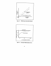
FTBSOO
integral signal conditioner will compensate for the frequen-
cy offset characteristics of the flowmeter, by using the method of offset
frequency injection. Offset frequency injection is implemented electronically
by adding a signal equal to the offset frequency required to linearize the out-
put of the flowmeter. This effectively shifts the output characteristic to that
of the desired ideal. A low-flow cutout feature is provided where the off-
set signal is inhibited during no flow to prevent false outputs from being
generated.
The FTB500 Series Turbine Meter is a family of low flow rate measurement
devices based on a
flowrate
which
does not pass through zero. left uncorrected, this will result in a K-factor
which varies with flow rate.
The
CMOS/lTL
compatible output. The attenuator produces a capacitor coupled AC out-
put which is suitable for driving other signal conditioners, indicators, or con-
trollers which require an AC signal input.
The output frequency from the FTB500 Series Turbine Meter versus flow
is essentially a straight line of frequency as a function of
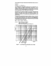
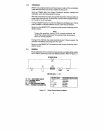
The signal entering the frequency to analog converter is passed through a
combination of divide by N and DIP switch matrix. The output is chosen
whose pulse rate is between 75 and 150 Hz at the maximum flow rate to
be measured. This scaled pulse rate is fed into a precision monostable cir-
cuit. The output of the monostable is then filtered into an analog voltage
that is proportional to flow.
The output amplifier will take this voltage and perform either a voltage to
voltage amplifier or voltage to current amplifier.
Finally, the output is divided by 8 to reduce irregular pulse spacing. Then,
the pulse train enters a buffer and an attenuator simultaneously. The buf-
fer output produces a square wave pulse which can be used as a