


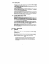
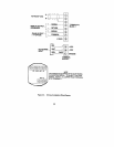
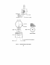
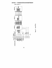

Potentiometer
locations
14
’
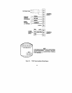
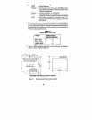
Figure 3-1.
Dimensions and
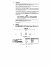
* EQUIPPED FOR ANALOG OUTPUT OPTION
mA
output, OV for 0 to
5v output.
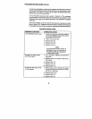
1.
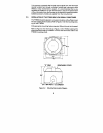
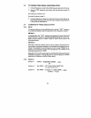
The Range Adjustment is accomplished by selecting a switch position
on a DIP switch located on the PCA-112 printed circuit card depending
on the model. Refer to Table 3-l to determine required switch position,
and select the switch position on the top printed circuit board adjacent
to the zero adjust potentiometer.
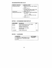
TABLE 3-1
RANGE SELECT SWITCHES
F (MAX)
RANGE SELECT
SWITCH
POSITION
300 to 600
3
600 to 1200
4
1200 to 2400
5
2400 to 4800
6
2.
Turn the “SPAN” potentiometer fully counter-clockwise until slippage
is felt or 25 turns. Refer to Figure 3-1.
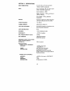
mA
for 4 to 20
mA
output, 5V for 0 to 5V output
ZERO
= fixed offset component of analog output. For
example, 4
mA
for 4 to 20
ifi,
PULSE/GAL
SPAN
= varying component of analog output. For example,
16
F(MAX)
was defined.
K Factor
= in units of readout,
R(MAXl when
at the reference condition at which the relation with
F(MAX)
= the flowmeter output frequency at
F(OSl
= offset frequency
F(TEST)
= test frequency used
where: