


#77-545-018 or equivalent on the insert.
NOTE
“0” ring should be lightly lubricated with “0” ring lubrication
wh ich is silicone based.
12.
P lace insert on the shaft. W hen properly seated gently push the
insert back on the shaft.
13.
Install and tighten the threaded plug. Tighten plug until snug. Do
not over tighten.
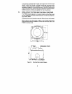
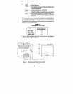
The flow m eter is ready for service W hen installing the flow m eter be sure
to orient the input and output correctly.
17
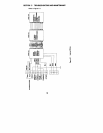
pelton
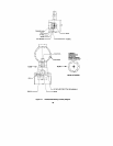
whee l faces the IN side of the
housing. Refer to Figure 4-1 detail.
NOTE
IF THE ROTOR IS INSTALLED BACKWARDS , THE METER W ILL
NOT G IVE YOU THE ACCURACY YOU REQU IRE . REFER TO THE
DETA IL CLOSELY.
Il.
Install a new Viton “0” ring
FTB500
Flow m eter m ust be held in place by a vise. Me ter orien-
tation should be such that the threaded plug is facing upwards.
Using a screwdriver and turning counter clockwise, break the seal and
re move the plug.
Using tweezers or needle nose pliers, slowly pull the insert out, while
taking care not to da m age the shaft or lose the thrust stop.
Remove the rotor by using a pair of tweezers.
Remove the shaft asse m bly with s m ooth needle nose pliers. Care
should be taken in not defor m ing the shaft and loss of any parts.
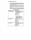
Exa m ine the flo wme ter internals for signs of corrosion or fouling by
foreign m aterials.
Exa m ine the shaft and bearings for signs of wear or corrosion on the
m ating surface.
If wear or corrosion is present in bearings, obtain new bearings fro m
stock of the m anufacturer.
Insert ball bearings in rotor.
10.
Gu ide the rotor bearing asse m bly onto the shaft. Make sure to orient
the rotor so the cup side of the
1.
2.
3.
4.
5.
6.
7.
8.
9.
The