


3 Installation
20 MiLLennium GPSCard and Enclosures Guide to Installation & Operation
•
protection from hostile physical environments (e.g. rain, snow, sand, salt, water, extreme temperatures)
•
protection from vibration conditions
•
electromagnetic shielding to protect from hostile RF environments (e.g. nearby transmitters)
•
electromagnetic shielding so that the final product itself conforms to RF emissions guidelines
•
protection from ESD
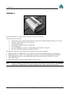
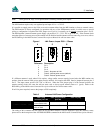
The MiLLennium card can be held in place by screws, card rails, or both. Please see Appendix B, Page 33 for
mechanical drawings.
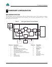
PREPARING THE DATA, SIGNAL & POWER HARNESS
The wiring harness provides the following interconnect functions:
•
access to COM1 and COM2 serial communications ports
•
access to input and output timing strobes
•
power input(s)
•
access to control signals
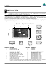
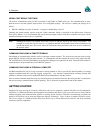
A 64-pin / 0.1" / DIN 41612 / Type B / female connector (e.g. Harting #0902 164 6825, #0902 264 6828, or equivalent)
is required to interface with connector P1 on the MiLLennium (see Figure 3 Typical System Configuration, Page 18).
The connectors you choose for interfacing to the power source(s), COM ports, and strobes will depend on your external
equipment requirements. Appendix E, EDGE-VIEW OF CONNECTOR P1, Page 65 shows the pin names and locations
on connector P1.
Note: See Appendix B, MILLENNIUM TECHNICAL , Page 33 for descriptions of the function of each connector
pin.
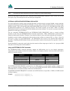
A MiLLennium GPSCard can function with the same 64-pin connector built for an OEM2 GPSCard (NovAtel’s second
generation receiver), which makes the upgrade simple. However, an OEM2 GPSCard will not function with a connector
built for a MiLLennium; this is because several pins on the OEM2 GPSCard are no longer used on the MiLLennium, as
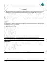
shown in Table 2:
Table 2 Disabled OEM2 Connector Pins
OEM2 Signal Name Connector Pin
-12VDC 3A
+12VDC 3B
SELA1 5 B
SELB1 6 B
NMEA Opto 1 7 B
TXD1(-)/NULL 8 B
SELA2 13 B
SELB2 14 B
NMEA Opto 2 15 B
TXD2(-)/NULL 16 B
External Power
See Appendix B, Page 33 for external power input connections:
• Digital ground
pins 1A/B (internally connected)
• Vcc, main power (+5 V DC)
pins 2A/B (internally connected)
• Optional external LNA power
pin 4B (≤ 30 V DC) and 4A (GND)