


2 Hardware Configuration
16 MiLLennium GPSCard and Enclosures Guide to Installation & Operation
•
supplies power to an active antenna through the coaxial cable while maintaining isolation between the DC and RF
paths. A hardware jumper configuration is provided to select an internal or external DC power supply for an active
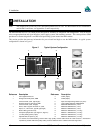
GPS antenna. See jumper P301 in the Chapter 3, I, Figure 3 (on page 18) and Figure 4 (on page 21).
The RF section can reject a high level of potential interference (e.g., MSAT, Inmarsat, cellular phone, and TV sub-
harmonic signals).
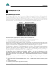
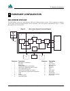
DIGITAL ELECTRONICS SECTION
The digital section of the MiLLennium receives down-converted, amplified GPS signals that it digitizes and processes to
obtain a GPS solution (position, speed, direction and time). The digital section consists of an analog-to-digital converter,
a 32-bit 25 MHz system processor, memory, control and configuration logic, signal processing circuitry, serial peripheral
devices, and supporting circuitry. I/O data and timing strobe signals are routed to and from the board via a 64-pin DIN
41612 Type B male connector. Two EIA RS-232C serial communications ports support user-selectable bit rates of 300 -
115,200 bps, with a default of 9600 bps. The digital section does the following:
•
converts the IF analog signals to a digital format
•
tracks the codes (C/A & P) and carrier phases of the L1 signals (and L2 signals with the appropriate MiLLennium
model) of the satellites in use
•
performs channel and loop control
•
performs position computation
•
executes navigation software
•
performs database management
•
monitors self-test system status
•
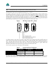
controls diagnostic LEDs: a red one which only lights up to indicate an error condition, and a green one (the
“heartbeat”) which blinks on and off at approximately 1 Hz to indicate normal operation.
•
controls I/O functions
The strobe signals are described as follows:
•
Mark input: this signal provides a time tag to the signal processors, which respond to a falling edge of the signal
provided from an external device. It can be enabled by you to provide a precise time and data output event.
•
Measure output: an output measurement rate which generates an active-periodic signal. This output is also routed to
the signal processors, where it provides a trigger for the measurement collection.
•
Variable-frequency (VARF) output: a user-programmable, variable-frequency pulse train
•
PPS output: a 1 ms pulse repeating at a 1 Hz rate that is used to synchronize the board with external devices.
•
Status output: an output that changes logic states when a valid GPS position is obtained
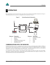
You configure the MiLLennium using special commands. In turn, the MiLLennium presents information to you in the
form of pre-defined logs in a number of formats. In addition, when two MiLLenniums are linked for differential
positioning, the reference and the remote stations can communicate directly through their serial ports.
COMMUNICATION PORTS
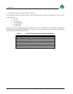
The default communications protocol for each port is as follows:
• RS232C
• 9600 bits per second
• no parity
• 8 bits
• 1 stop bit
• no hand shaking
• echo off