


2 – Set Up
DL™ User Manual Rev 3 23
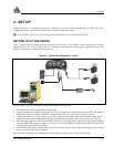
For further information on the following topics, see the following sections of this manual:
• For a listing of the required input supply voltages, and the typical power consumption in logging and “sleep”
modes, see the Power Requirements section of Appendix B, Page 37.
• For pin-out information on the 4-pin power connector, see Table 9: Power Connector Pin Assignment, Page 41.
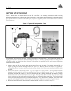
• For a listing of the voltage levels at which the Power indicator changes color, or at which the DL switches from
one source to another, or at which the DL shuts off, see the Power Management section of Appendix B. These
events are described in Table 4: Status Indicators - Meaning, Page 26.
• See Appendix H - Replacement Parts, Page 87, if you need to consult the list of NovAtel and LEMO part
numbers.
Using a Non-NovAtel Power Cable
If you decide to use a power cable that was not supplied by NovAtel, or make your own, there are a few things that you
should keep in mind. There will always be a drop in voltage between the power source and the power port that is due to
cable loss. Improper selection of wire gauge can lead to an unacceptable voltage drop at the DL. A paired wire run
represents a feed and return line; therefore, a 2-m wire pair represents a total wire path of 4 m. For a DL operating from a
12 V DC battery system, a power cable longer than 2.1 m (7 ft) should not use a wire diameter smaller than that of 24
AWG.
USING THE REMOVABLE FLASH MEMORY CARD
Data can be logged to a PC Card, a flash-memory module which you can access, exchange and replace when needed.
The need for a companion handheld data logger is avoided when continuous user interaction is not required, since DL is
capable of logging data according to pre-configured parameters without any user intervention. In applications when
continuous user interaction is required, such as in GIS surveying, a simple handheld controller can be used with DL, as
the controller does not require its own data logging memory. The reduced handheld data logger or controller
requirements simplify your system and reduce its total cost and power consumption.
The access door on the DL’s front end cap provides a water and dust-resistant seal around the PC Card. The cover latch
must be rotated a ¼-turn in order for the cover to seal properly. When the cover is closed and latched, the enclosure is
sealed to provide protection against adverse environmental conditions.
WARNING: To minimize the possibility of damage, always keep this cover closed and latched except when
exchanging PC Cards.
Collected data can either be transmitted to a host computer over a serial port, or stored on the PC Card. If you choose to
log data to the PC Card, each logging session is stored in a single, unique file. These files can then be transferred to a
host computer, for data analysis or other types of post-processing, by one of two methods:
• transfer the data by means of serial communications
• physically remove the PC Card from the DL and insert it into the host computer, provided that it is also suitably
equipped with a PC Card port
You have the flexibility of choosing the PC Card with the storage capacity that is the most appropriate for your needs,
based on the selected logging rate. This is discussed in greater detail in Data Storage Requirements, Page 30.
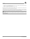
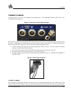
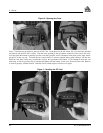
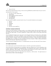
Figure 6 illustrates the procedure to unlock the cover. In the photo on the left, the latch is in the “locked” position. In the
photo on the right, the latch is being rotated counter-clockwise into the “unlocked” position. To lock the cover, rotate the
latch clockwise. If it resists turning, do not force it; rather, open and close the cover, then try again.