


2 – Set Up
DL™ User Manual Rev 3 19
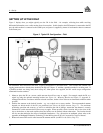
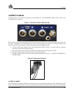
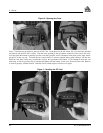
CONNECT CABLES
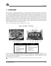
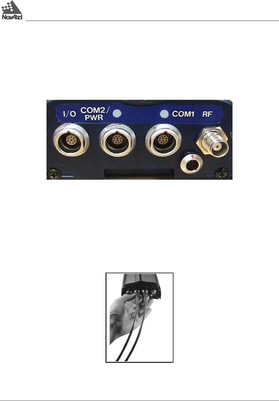
As shown in Figure 4, on the rear end-cap there are four labeled ports – I/O, COM2/PWR, COM1, and RF. There is also
an unlabelled power input port.
Figure 4: Close-up of Ports on Rear End-cap
Each connector is keyed to ensure that the cable can be inserted in only one way, to prevent damage to both the DL and
the cables. Furthermore, the connectors that are used to mate the cables to the DL have a locking mechanism that
requires careful insertion and removal. Observe the following when handling the cables.
• To insert a cable, make certain you are using the appropriate cable for the port – the serial cable has a different
connector (10 pin) than the I/O cable (8 pin).
• Line up the red dot on the connector shell with the red index mark on the receptacle on the DL.
• Insert the connector until it seats with a click; it is now locked in place.
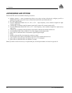
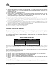
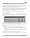
• To remove a cable, grasp the connector by the knurled ring and pull (see Figure 5). DO NOT PULL DIRECTLY
ON THE CABLE.
Figure 5: Removing a Connector
I/O PORT & CABLES
DL incorporates an input/output (I/O) port, which allows access to the Mark input, Measure output, VARF output, 1PPS
output, and STATUS output signals. These are specialized signals that are used when the DL is part of an interconnected