


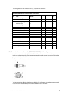
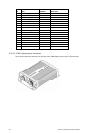
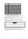

Pin
Color AWG Size Signal name
1 Blue / Gray (big) #16 Motor Ground
2 Purple / Brown (big) #16 Motor Ground
3 White / Orange (big) #16 Motor Power
4 Red / Green (big) #16 Motor Power
5 Black / Sky (big) #16 Scanner Ground
6 Black #22 Analog Ground
7 Drain wire (coax line) #24 Video Ground
8 No connection
Not used
9 Yellow / Pink (big) #16 Scanner Power
10 Axis line #24 Video
11 Yellow (thin) #24 RS-485 Comm+
12 Green (thin) #24 Bearing Zero
13 White (thin) #24 RS-485 Comm-
14 Drain wire #24 Trigger Ground
15 Shield line #24 Trigger
16 Orange (medium) #22 Bearing Pulse
Shell Braid shield
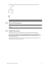
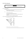
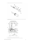
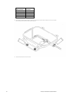
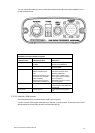
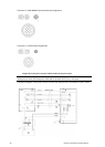
3.10.3.4 10 kW radar processor connectors
There are four interface connectors on the rear of the 10kW radar processor, plus a Chassis Earth.
Northstar 10 kW Radar Installation Manual
24