


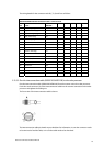
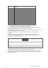

The wiring details for the connector ends B, C, D, E, and F are as follows:
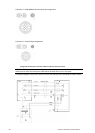
NS003105/NS003106 Interconnection cable - connector ends
Pin Color AWG Size B C D E F
1 Blue / Gray (big) #16
1
2 Purple / Brown (big) #16
1
3 White / Orange (big) #16
2
4 Red / Green (big) #16
2
5 Black / Sky (big) #16
1
6 Black #22
6
7 Drain wire (coax line) #24 2
8 No connection
9 Yellow / Pink (big) #16
2
10 Axis line #24 1
11 Yellow (thin) #24 3
12 Green (thin) #24
5
13 White (thin) #24 4
14 Drain wire #24
2
15 Shield line #24
1
16 Orange (medium) #22
3
Shell Braid shield
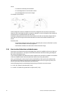
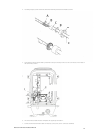
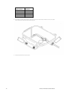
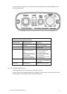
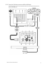
3.10.3.3 Run the interconnection cable (NS003105/NS003106) to the radar processor
Run the interconnection cable (NS003105/NS003106) from the scanner unit to the radar processor.
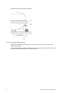
Push the round connector (A) of the interconnection cable into the scanner connection on the radar
processor and tighten the locking nut.
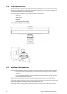
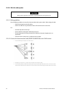
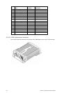
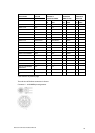
The front view of the interconnection cable is shown:
The interconnection cable pin details are provided here for information, in case the connector needs
to be removed to feed the cable, or in case the cable needs to be shortened.
Northstar 10 kW Radar Installation Manual
23