


7
ON
OFF
1 2 3 4 5 6 7 8
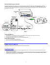
Dipswitches
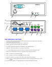
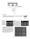
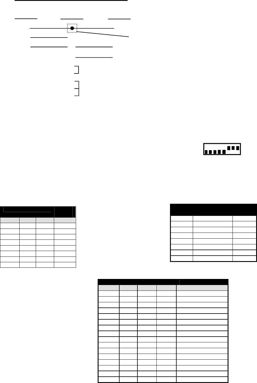
The dipswitches located next to the RS232 connection (Fig. 8) are used to configure the baud rate and
address of the KEEMUX. The default baud rate is 9600. The default address is 1. Use the charts
below to change the baud rate and address as needed.
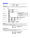
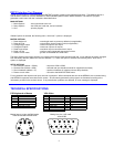
DIP SWITCH
The unit powers up with a default
baud rate of 9600 and a fixed data
protocol of 8 data bits, no parity, and
1 stop bit. To change the baud rate,
unit address, and loop back (more on
the unit address and loop back later),
an 8-SPST DIP switch on the panel
near the DB-9 connectors can be
used. This table shows the DIP switch
functions and their default positions.
SWITCH FUNCTION
DEF-
AULT
1 loop back ON
2 baud rate 0 ON
3 baud rate 1 ON
4 baud rate 2 ON
5 unit address 0 ON
6 unit address 1 OFF
7 unit address 2 OFF
8 unit address 3 OFF
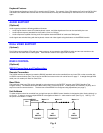
BAUD RATE
The baud rate can be
changed by powering
down the unit,
changing the DIP
switch, and then
powering back up.
This table shows how
to set the baud rate.
DIP SWITCH BAUD
RATE
4 3 2
OFF OFF OFF 300
OFF OFF ON 600
OFF ON OFF 1200
OFF ON ON 2400
ON OFF OFF 4800
ON OFF ON 9600
ON ON OFF 9600
ON ON ON 9600
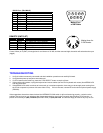
DIP SWITCH UNIT ADDRESS
8 7 6 5
OFF OFF OFF OFF 0 (not valid)
OFF OFF OFF ON 1
OFF OFF ON OFF 2
OFF OFF ON ON 3
OFF ON OFF OFF 4
OFF ON OFF ON 5
OFF ON ON OFF 6
OFF ON ON ON 7
ON OFF OFF OFF 8
ON OFF OFF ON 9
ON OFF ON OFF 10
ON OFF ON ON 11
ON ON OFF OFF 12
ON ON OFF ON 13
ON ON ON OFF 14
ON ON ON ON 15
UNIT ADDRESS
To allow multiple units to be controlled from a single host
port, the remote interface is designed to allow "daisy
chaining" of up to 15 units. By setting the appropriate
DIP switches, each unit can be given a unique address
(1-15). Then the unit will only respond to commands on
the bus if its address is embedded in the command. The
"loop back" DIP switch should be ON for the last unit in
the chain, and OFF for all other units. If only one unit is
being controlled, DIP switch 1 should be left ON. This
table shows how to set the unit address.
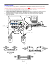
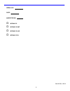
(Unit #1)
(Source)
23
33
555
22
7
8
1
4
6
Jumper
Jumpers
Not connected to
source connector
(Unit #2)
9D Female9D Male 9D Male
Wiring Schematic of Matrix-Y-1 cable
Fig. 7
Fig. 8