


3
INSTALLATION
1. Turn OFF power to all CPUs that will be connected to the NTI Switch before connecting or disconnecting any cables.
WARNING! Damage to the CPU may result if power is not turned OFF before connecting or disconnecting cables.
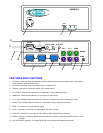
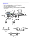
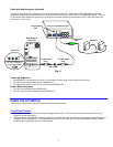
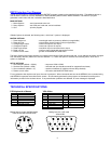
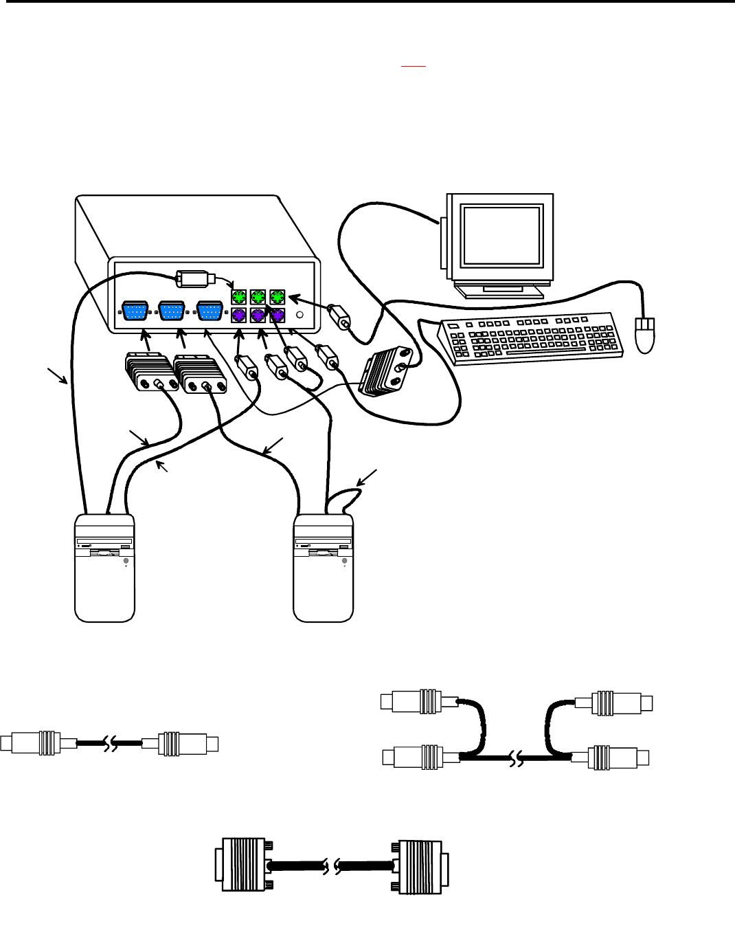
2. Connect PS/2 keyboard to “USER KEYBD” port on the rear panel of the switch. (See Fig. 1)
3. Connect PS/2 mouse to “USER MOUSE” port on the rear of the switch.
4. Connect monitor to “MONITOR” port on the rear of the switch.
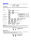
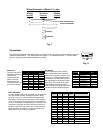
5. Using (1) VVKINT-xx-MM or (2) VKINT-xx-MM or VKEXT-xx-MM cables (Fig. 2 & 3, required, not supplied), connect the
keyboard and mouse ports of a PS/2 CPU to “PC 1 KEYBD” and “PC 1 MOUSE” ports on the rear of the switch.
6. Using VEXT-xx-MM (Fig. 4, required, not supplied), connect the video port of a PS/2 CPU to “PC 1 VIDEO” port
on the rear of the switch.
7. Repeat steps 5 & 6 for connecting a second CPU to the remaining ports on the rear of the switch.
Male
6 pin miniDIN
PS/2
Male
6 pin miniDIN
PS/2
VKINT-6/10-MM
VKEXT-25/50-MM
Male
6 pin miniDIN
PS/2
Male
6 pin miniDIN
PS/2
VVKINT-3/6/10/15/25/50-MM
Male
15HD
VGA
Male
15HD
VGA
VEXT-3/6/10/15/25/35/50/75/100-MM
Fig. 4
Fig. 3
Fig. 2
Fig. 1
VGA
Multi-Scan
Monitor
PS/2 Keyboard
VEXT-xx-MM
VEXT-xx-MM
VKINT-xx-MM
VVKINT-xx-MM
VKINT-xx-MM
PS/2 Mouse
PC 2 VIDEO
12
43
65
USER
12
43
65
12
43
65
PC 1 VIDEO
MONITOR
PC 1 PC 2
PWR
12
43
65
12
43
65
12
43
65
MOUSE
KYBD
Rear View of KEEMUX-P2
P
S
2
C
P
U
P
S
2
C
P
U