


8
RS232 Interface Test Program
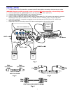
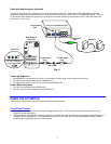
RS232 communication is configured using the RMTEST program, located on the supplied floppy disk. This software allows a
user to test the functions of an NTI KEEMUX or Multi-user/Multi-platform switch RS232 interface. The RMTEST program
generates a main menu with the 3 selections described below:
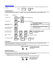
MAIN OPTIONS
1. Matrix Options - send commands to the unit.
2. Setup Options - set COM port, baud rate, and unit address
3. Quit - quit the program
If Matrix Options is selected, the following menu, which has 7 options, is displayed:
MATRIX OPTIONS
1. Reset single unit - reset single matrix to power-up defaults (not applicable)
2. Reset all units - reset all daisy chained matrix units (not applicable)
3. Change single output - connect an input to one output
4. Change all outputs - connect an input to all outputs
5. Read single output - read which input is connected to an output
6. Read unit size - read how many inputs and outputs the unit has
7. Return to main menu - go back to the MAIN OPTIONS menu
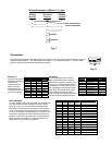
The Setup Options main menu selection only needs to be executed if the switches baud rate or unit address have been changed
from the factory defaults ( 9600 baud, and unit address = 1). When this option is selected, the following menu, which has 4
options, is displayed:
SETUP OPTIONS
1. Set COM port (default = COM1) - set port to COM1-COM3
2. Set baud rate (default = 9600) - set baud rate (see interface manual for supported baud rates)
3. Set unit address (default = 01) - set the unit address (if multiple units are daisy-chained)
4. Return to main menu - Go back to the MAIN OPTIONS menu
For any selection that requires user input, the user is prompted. When commands are sent to the KEEMUX, the command string
and KEEMUX responses are echoed to the screen. All commands generated by the program are formatted according to the
information provided in the sections above. If any transmission problems are detected, an error message is displayed.
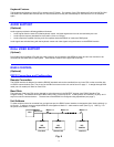
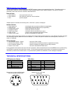
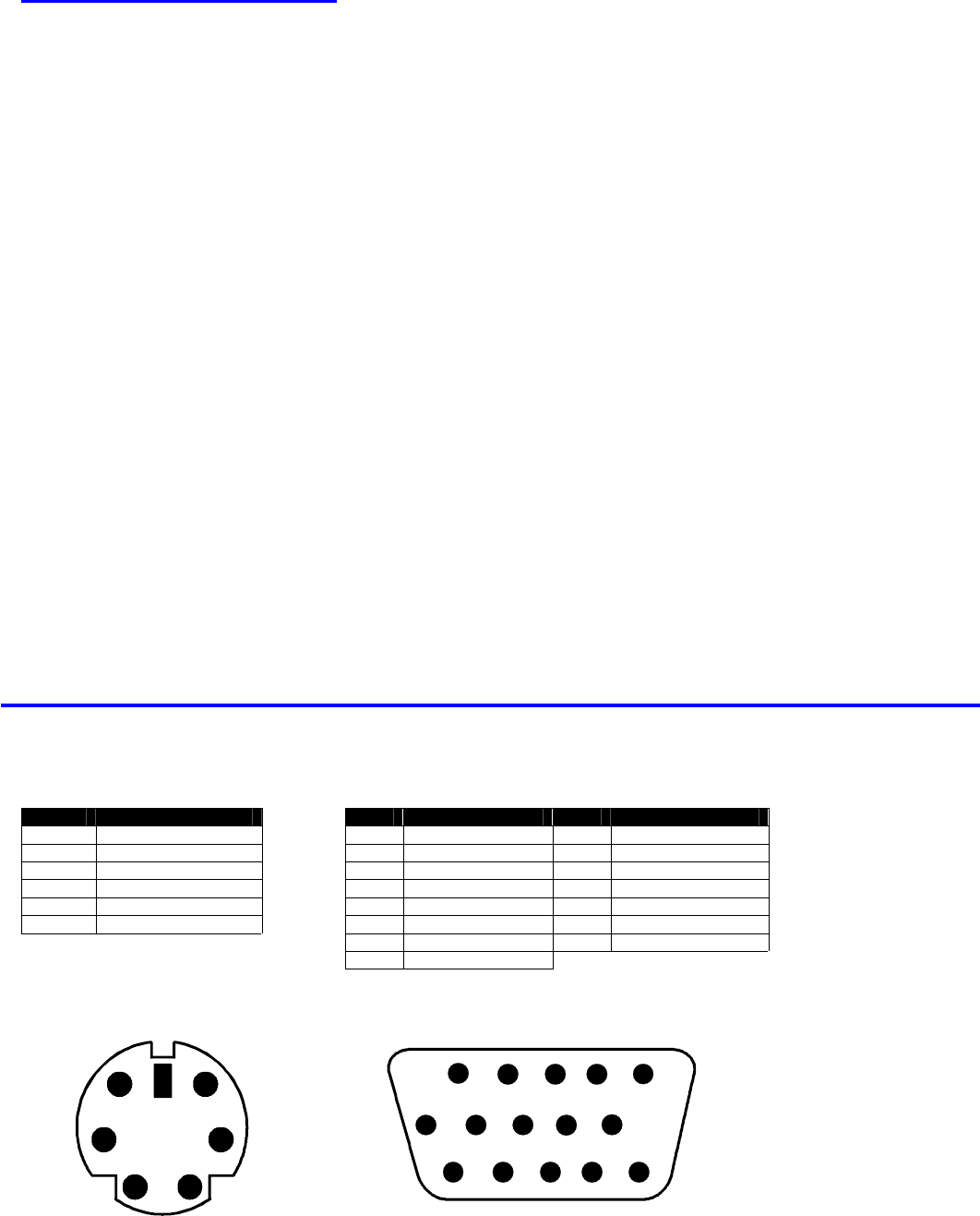
TECHNICAL SPECIFICATIONS
PS2 Keyboard or Mouse VGA Video
Pin # Signal PIN# Signal Pin # Signal
1 KYBD DATA 1 RED 9 NC
2 MOUSE DATA 2 GREEN 10 GND
3 GND 3 BLUE 11 ID0
4 +5 4 ID2 12 ID1
5 KYBD CLOCK 5 TST 13 HS
6 MOUSE CLOCK 6 RED GND 14 VS
7 GREEN GND 15 NC ID3
8 BLUE GND
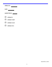
Mating face of a 6 pin miniDIN female
PS/2 KEYBOARD AND MOUSE
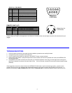
Mating face of a 15HD male
VGA VIDEO
1 2 3 4 5
6 7 8 9 10
11 12 13 14 15
2
1
4 3
6
5