


35
TRACKER 5600 Installation and Operation Manual
NAVMAN
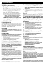
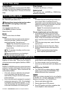
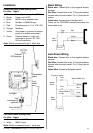
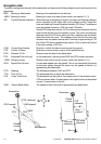
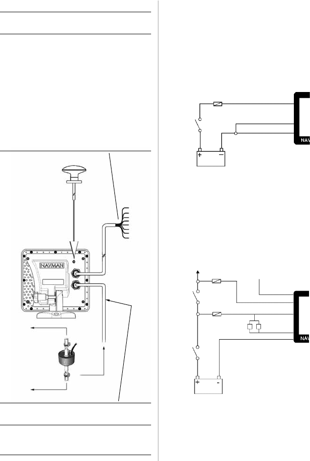
External
GPS antenna
Fuel
transducer(s)
(optional)
Installation
To engine
From fuel tank
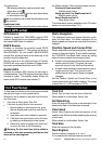
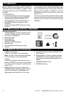
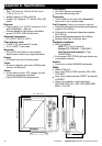
Auto Power Wiring
Black wire: Connect this to the negative battery
terminal.
Red Wire: Connect this to the 12 V positive battery
terminal after the main switch. Fit a 1 Amp fuse as
shown.
Yellow Wire: Connect to the ignition switch.
Fuse
Fuse
White (NMEA out)
Green
External Beeper
or Light
Red
Yellow
Black
Main
switch
12 V DC
Ignition
switch
To ignition system
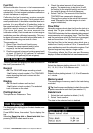
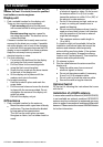
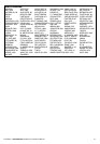
Basic Wiring
Black wire: Connect this to the negative battery
terminal.
Red Wire: Connect this to the 12 V positive battery
terminal after the main switch. Fit a 1 Amp fuse as
shown.
Yellow wire: Connect this to the black wire.
Power on the TRACKER manually whenever the
main switch is on.
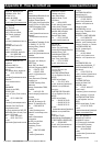
Power/data cable (black locking collar)
Pin Wire Signal
1 Black Ground (power negative, NMEA)
2 Brown Power out, 9 V DC
3 White NMEA out, to autopilot/radar
4 Blue NavBus - or NMEA 2 input
5 Red Positive power in, 11 to 16.6 V DC
6 Orange NavBus +
7 Yellow Auto power in (connect to positive
power in to enable auto power)
8 Green External beeper or light out,
switched to ground, 30 V DC,
200 mA maximum
Note: Shield is connected to pin 1, black wire
Fuse
Red
Yellow
Black
Main
switch
12 V DC
Power/data
cable
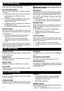
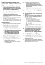
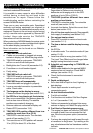
Fuel cable (white locking collar)
Pin Wire Signal
1 Black Ground (NMEA)
3 White NMEA1 input
Note: Shield is connected to pin 1, black wire
Fuel
cable