


Chapter 3 Signal Connections
© National Instruments Corporation 3-9 NI PCI-8254R User Manual
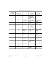
Note TRIG 0, TRIG 1, and TRIG 2 signals are not accessible through the standard 44- to
37-pin cable and I/O terminal block.
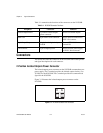
NI Vision I/O Terminal Block and Prototyping Accessory
Use the NI Vision I/O Terminal Block and Prototyping Accessory to
troubleshoot and prototype digital I/O applications for the NI 8254R, the
NI 8255R, and the NI CVS-1450 Series compact vision system. The
NI Vision I/O Terminal Block and Prototyping Accessory provides screw
terminals for easy connections and LEDs for each signal.
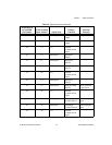
Note TRIG 0, TRIG 1, and TRIG 2 signals are not accessible through the standard 44 to
37-pin cable and NI Vision I/O Terminal Block and Prototyping Accessory.
Power Requirements
This section describes the power requirements of the NI 8254R.
Isolated Outputs Power Connector
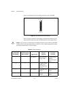
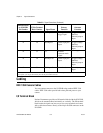
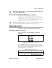
Figure 3-3 illustrates the isolated outputs power connector on the
NI 8254R.
Figure 3-3. NI 8254R Isolated Power Connector
The isolated outputs power connector on the NI 8254R accommodates one
power supply. The V terminal provides the isolated output circuitry (5 to
30 VDC) for the NI 8254R. The C terminal provides the common-mode
signal for the NI 8254R, as shown in Table.
Table 3-4. Power Connector Terminals
Terminal Description
V Isolated power (5 to 30 VDC)
C Isolated common-mode signal
VC