


© National Instruments Corporation 2-1 NI PCI-8254R User Manual
2
Hardware Overview
Digital I/O
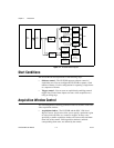
The digital I/O functions on the NI 8254R are accessible through 2 TTL
inputs, 10 TTL outputs, 13 isolated inputs, and 4 isolated outputs.
You can use input signals as triggers, product selection ports, change
detectors, or to read quadrature encoders. Uses for output signals include
controlling camera reset and exposure, controlling strobe lighting,
outputting inspection results, or communicating with PLCs. You can also
define the functions of digital input and output signals.
For information about how to use LabVIEW to implement specific digital
I/O functions, refer to the examples at
<LabVIEW>\examples\IMAQ\
IMAQ IO.llb
, where <LabVIEW> is the location in which LabVIEW is
installed. For information about how to use C or Visual Basic to implement
specific digital I/O functions, refer to the examples at
<National Instruments>\NI-IMAQ IO\Examples\.
For more information about using the LabVIEW FPGA Module to
implement custom FPGA logic, refer to the examples at
<LabVIEW>\
examples\IMAQ\IMAQ IO FPGA.llb
, where <LabVIEW> is the location
to which you installed LabVIEW.
RIO and The LabVIEW FPGA Module
Behind the digital I/O of the NI 8254R is an FPGA which has been
preconfigured with the functionality required for most common machine
vision tasks. If the factory configured functionality does not fulfill your
requirements, the FPGA is user-configurable with the LabVIEW FPGA
Module. RIO allows you to develop custom FPGA logic to add triggering,
pulse-width modulation signals, or custom communications protocols to
your machine vision application.