


Chapter 3 Signal Connections
NI PCI-8254R User Manual 3-4 ni.com
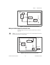
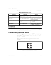
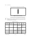
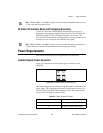
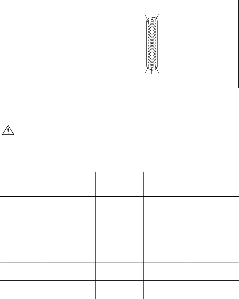
Figure 3-2 illustrates the 44-pin D-SUB connector on the NI 8254R.
Figure 3-2. NI 8254R 44-Pin D-SUB Connector
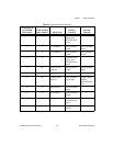
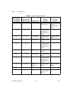
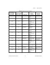
Table 3-3 lists pin numbers, signal names, and signal descriptions for the
44-pin D-SUB connector on the NI 8254R and the 37-pin terminal block.
Caution Do not draw more than 500 mA combined from the V pins on the 44-pin D-SUB
connector. Do not draw more than 100 mA from 24 V or 30 V isolated outputs. Do not draw
more than 50 mA from 5 V isolated outputs.
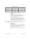
Table 3-3. Signal Connections
44-Pin D-SUB
on NI 8254R
Pin Number
37-Pin Terminal
Block Number
Signal Name
Primary
Function
Alternate
Function
1 1 TTL Input 0 Pulse generator
trigger input
Trigger Change
Detector,
General-purpose
input
2 3 C Common-mode
signal of the
NI 8254R main
power
—
3 4 TTL Output 0 Watchdog timer
output
General-purpose
output
4 5 TTL Output 1 Pulse generator
output
General-purpose
output
11631
153044