


PAGE 18 — G-55H GASOLINE VIBRATOR — OPERATION & PARTS MANUAL — REV. #0 (03/07/06)
G-55H GASOLINE VIBRATOR — OPERATION
Operation
Read
all the safety instructions carefully. Safety instructions
will be found throughout this manual and on the vibrator motor.
Keep all safety information available, accessible, and in good,
readable condition.
■
Make certain that the flexible shaft is properly attached
to the motor and the head to the flexible shaft.
■
Use the flexible shaft in as straight a position as possible.
■
Do not bend the flexible shaft sharply at any point.
Sharp bends may cause a permanent kink, requiring
early replacement of the flexible shaft.
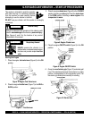
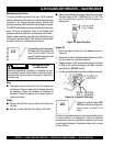
Connecting the vibrator head to the flexible shaft
1. Clean the mating parts threads with Loctite Primer “T”.
2. Allow to dry several minutes before applying a ring of
Loctite No.271 to the middle of the casing threads.
3. Screw the head tightly to the flexible shaft casing and
wait for 1 hour before using. The threads are left hand,
turn counter-clockwise to tighten. An equivalent brand
of anaerobic sealant may be used.
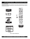
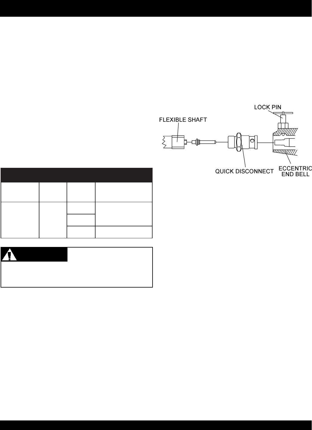
Figure 13. Couplings
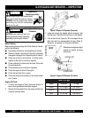
The G-55H Gasoline Vibrator, flexible shafting, and head
are shipped from the factory ready for assembly. Follow the
instructions listed below when connecting these parts before
using the gasoline vibrator.
Using head attachments not listed above may create a
hazardous condition when using the vibrator.
Equipment Combination Information
The following Equipment Combination Chart shows all of
the recommended connections between the gasoline vibrator
and the vibrator head.
SNOITANIBMOCTNEMPIUQE.5ELBAT
GNILPUOCTFAHSDAEH
TFAHSXAM
HTGNEL
D.QV283V283
.biv0041
)mc3.231(.tf82
.biv0071
.biv0012)mc2.99(.tf12
WARNINGWARNING
WARNINGWARNING
WARNING
Equipment Hazard
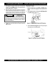
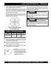
Connecting the 382V Flexible Shaft
1. Connect the 382V Flexible Shaft to the Quick Disconnect
coupling (Figure 13).
2. Pull UP on the lock pin and slide the shaft and quick
disconnect assembly into the eccentric end bell and
release the lock pin.
3. Twist the shaft assembly to make sure that the lock pin
is seated in one of the 3 tapered holes on the quick
disconnect coupling.