


MANUAL TRANSMISSION (E-W) -
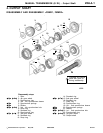
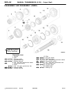
Output Shaft
22A-4-6
PWEE9508
E
May 1995Mitsubishi Motors Corporation
"
D
A
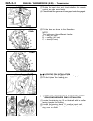
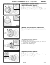
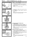
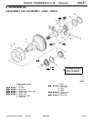
1ST - 2ND SYNCHRONIZER HUB INSTALLATION
(1) Place the hub on a workbench.
(2) Locate the synchronizer sleeve on the hub with the groove
for the selector fork facing up; see the illustration.
(3) Locate the three synchronizer springs together with the
rollers in the hub.
NOTE
Always use new synchronizer springs.
(4) Locate the hub together with the synchronizer sleeve
on the shaft.
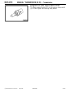
(5) Fit a new snap ring 8 <F5MR1, F5MR2> or synchronizer
ring <F5MR3>.
NOTE
Make sure that the lugs of the synchronizer ring engage
the recesses in the synchronizer sleeve.
"
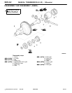
E
A
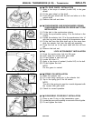
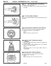
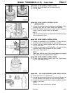
2ND GEAR WHEEL BEARING BUSH
INSTALLATION
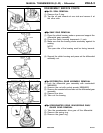
(1) Locate the bearing bush so that the oil passages of the
bearing bush and the output shaft are opposed.
(2) Place the heated bearing bush, using a pair of gripping
pliers, over the output shaft on the synchronizer hub.
NOTE
Allow the bearing bush to cool and then lubricate copiously
with transmission fluid.
"
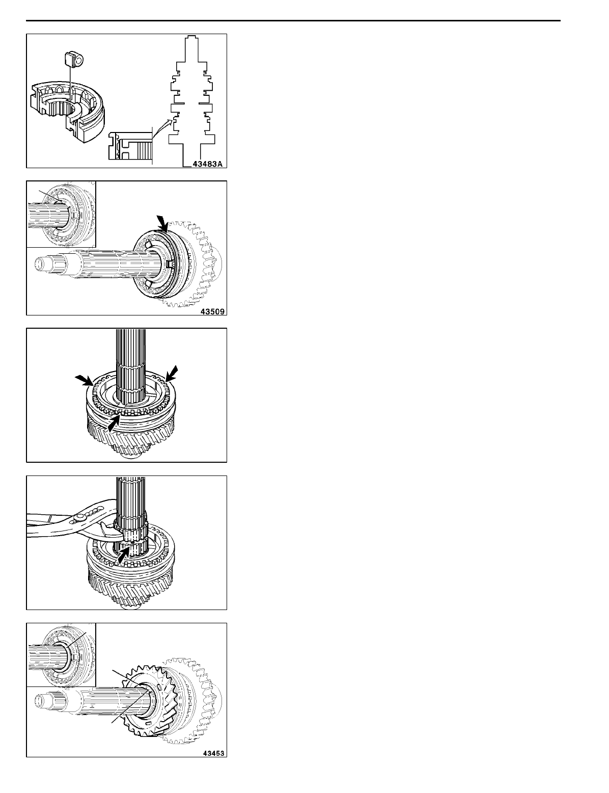
F
A
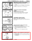
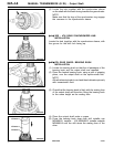
2ND GEAR WHEEL INSTALLATION
(1) Locate the serrated ring 7 (thickness: 1.5 mm) with the
bevelled edge facing towards the gear wheel.
(2) Locate the gear wheel together with the synchronizer
ring on the shaft.
(3) Fit the serrated ring 6 (thickness: 2.5 mm) with th e bevelled
edge facing towards the gear wheel.
(4) Fit a new snap ring 5.
NOTE
Make sure that the lugs of the synchronizer ring engage
the recesses in the synchronizer sleeve.
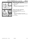
8
<F5MR1, F5MR2>
RMT0033
<F5MR3>
RMT0034
AddedPWEE9508-BMitsubishi Motors Corporation
May 1996
E
5
6
7