


MANUAL TRANSMISSION (E -W) -
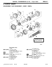
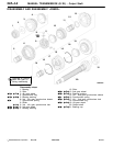
Output Shaft
22A-4-3
PWEE9508
E
May 1995Mitsubishi Motors Corporation
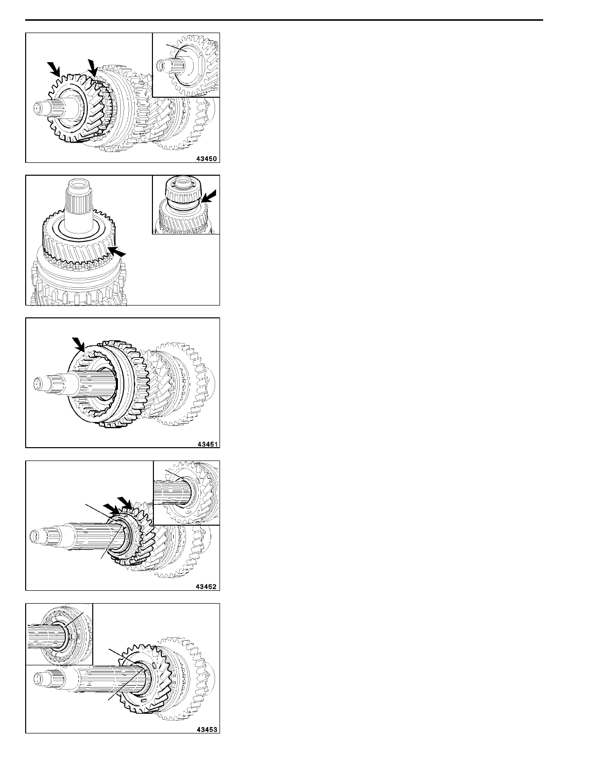
DISASSEMBLY SERVICE POINTS
A
A
"
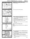
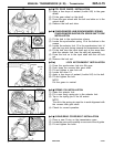
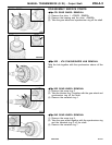
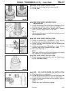
4TH GEAR WHEEL REMOVAL
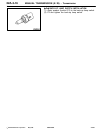
(1) Remove the shim 1. <F5MR1, R5MR2>
(2) Remove the bearing and the shim. <F5MR3>
(3) Take the gear wheel and synchronizer ring off the shaft.
A
B
"
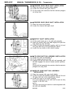
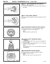
3RD - 4TH SYNCHRONIZER HUB REMOVAL
Take the hub together with the synchronizer sleeve off the
shaft.
A
C
"
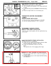
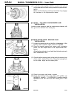
3RD GEAR WHEEL REMOVAL
(1) Remove the snap ring 2.
(2) Take the blocker ring 3 together with the gear wheel and
synchronizer ring off the shaft.
(3) Remove the serrated ring 4.
A
D
"
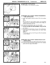
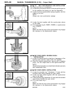
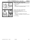
2ND GEAR WHEEL REMOVAL
(1) Remove the snap ring 5.
(2) Take the gear wheel together with the synchronizer ring
and the serrated ring 6 off the shaft.
(3) Remove the serrated ring 7.
1
<F5MR1, F5MR2>
<F5MR3>
RMT0025
RevisedPWEE9508-BMitsubishi Motors Corporation
May 1996
E
2
3
4
5
6
7