


MANUAL TRANSMISSION (E -W) -
Transmission
22A-3-11
PWEE9508
E
May 1995Mitsubishi Motors Corporation
"
G
A
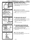
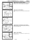
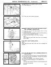
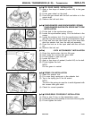
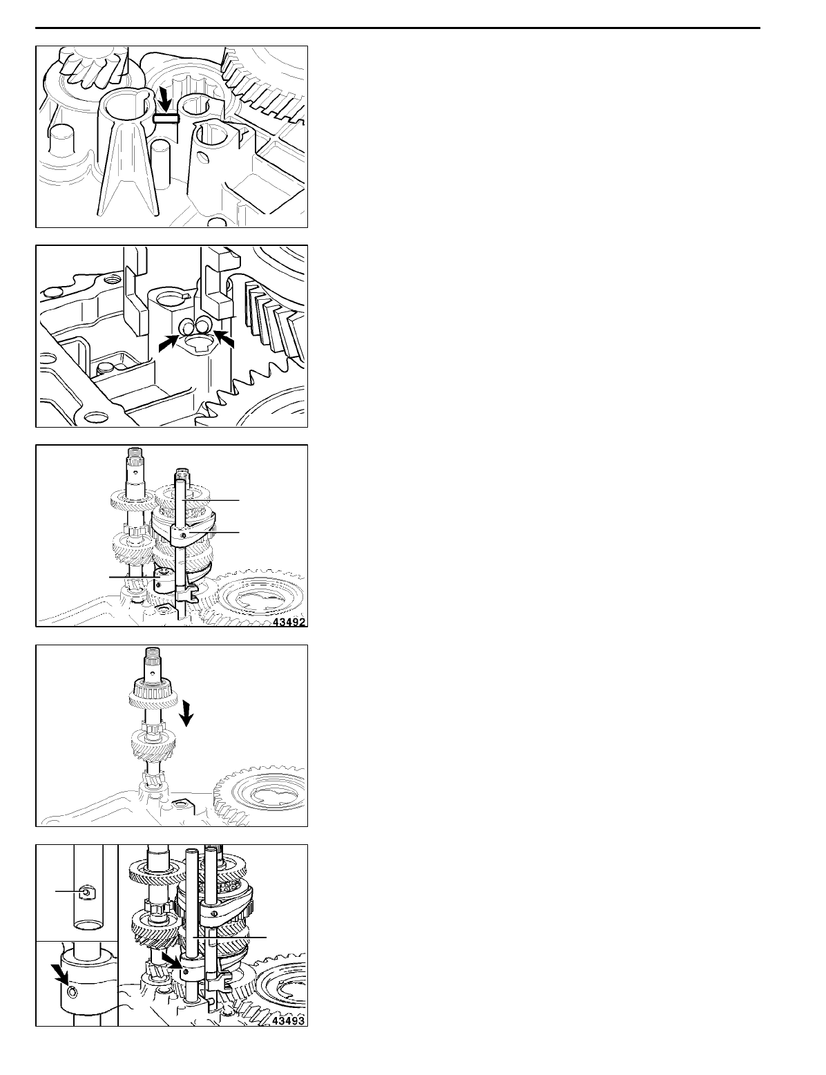
INTERLOCK PLUNGER INSTALLATION
(1) Fit the dowel pin.
(2) Fit the two short interlock plungers.
"
H
A
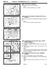
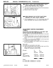
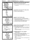
INPUT SHAFT/OUTPUT SHAFT/3RD AND 4TH SHIFT
RAIL ASSEMBLY INSTALLATION
(1) Locate the 1st and 2nd gear selector fork 3 in the
synchronizer hub.
(2) Locate the shift rail assembly 4 together with th e selector
fork 5 in the synchronizer sleeve.
(3) Locate the three shafts in the clutch housing.
NOTE
When fitting the input shaft, take care not to damage
the oil seal.
"
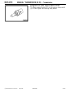
I
A
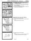
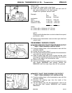
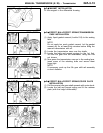
INPUT SHAFT INSTALLATION
NOTE
When fitting the input shaft, take care not to damage the
oil seal.
"
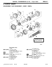
J
A
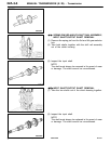
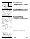
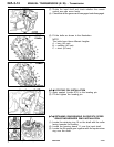
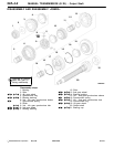
1ST AND 2ND SHIFT RAIL ASSEMBLY/SPRING PIN
INSTALLATION
(1) Fit the small interlock plunger 6 in the shift rail assembly.
(2) Introduce the shift rail assembly 7 through the selector
fork in the housing.
(3) Check the operation of the interlock plungers.
(4) Fit a new (short) spring pin in the selector fork.
NOTE
The slit in the spring pin must b e in axial alignment with
the shift rail assembly.
RevisedPWEE9508-BMitsubishi Motors Corporation
May 1996
E
RMT0015
RMT0016
3
4
5
RMT0017
6
7