


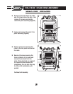
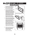
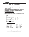

Place one of the ISO spacer brack-
ets and the left factory mounting
bracket (Removed from radio during
disassembly) on the left side of the
ISO units. (The spacer bracket
should be between the ISO units
and the factory bracket.) Align the
pins on the trim-plate with the
holes on the factory bracket and
mount the factory bracket to the
ISO units using screws supplied
with the radio.
(Figure A)
4
99-7402
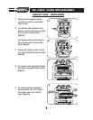
KIT ASSEMBLY
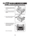
Continue to final assembly.
Place the double DIN trim-plate on
the front of the two ISO units.
(Figure A)
1
2
A
B
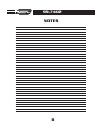
TWO STACKED ISO MOUNT UNITS
6
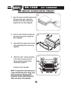
Attach the assembled units and
brackets to the radio trim panel using
the factory screws removed during
disassembly.
(Figure B)
3
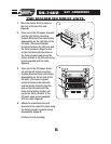
Place one of the ISO spacer brackets
and the right factory mounting
bracket (Removed from radio during
disassembly) on the right side of the
ISO units. (The spacer bracket
should be between the ISO units and
the factory bracket.) Align the pins
on the trim-plate with the holes on
the factory bracket and mount the
factory bracket to the ISO units using
screws supplied with the radio.
(Figure A)