


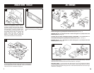
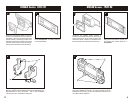
Disconnect the negative battery terminal to
prevent an accidental short circuit. Remove
(4) Phillips screws above the radio opening.
Remove (1) Phillips screw below the left side of
the radio opening. Remove (1) Phillips screw
from each side of the dash trim bezel. Pull off
the climate control knobs and remove the
climate control trim panel. Remove the
ashtray and lift the dash trim bezel off.
Remove (4) Phillips screws securing the
factory head unit and disconnect the wiring.
1
NISSAN 200SX 1980-83
2
3
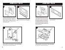
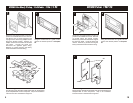
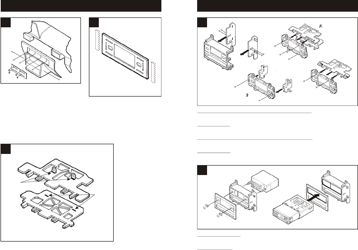
Using the scored lines as a guide, cut and
remove the dashed portions of Faceplate
#2.
Slide Mounting Tabs #5 into slots "A" on Brackets #13 and #14.
The Mounting Tabs, Brackets and Bracket slots can be identified
by the stamped letter on each component. Skip to the Installation
Instructions for ALL VEHICLES on Page #14.
1
14
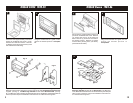
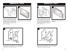
2-SHAFT HEAD UNITS: Snap the Faceplate onto the front of the Radio Housing. Slide the
aftermarket head unit into the kit and secure with shaft nuts. (see Fig. A)
DIN HEAD UNITS: Cut and remove the shaft supports from the Faceplate and Radio
Housing. Snap the Faceplate onto the front of the Housing. Slide the DIN cage into the kit and
secure by bending the metal locking tabs down. Slide the aftermarket head unit into the cage
until secure. (see Fig. B)
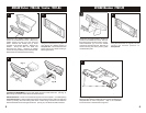
MAXIMA 1987-91, PULSAR 1987-90, STANZA 1987-89, 240SX: Mount Bracket Set #9 to
Radio Housing #1 with (4) Phillips Pan-head Screws supplied. (see Fig. A)
SENTRA 1987-90: Mount Bracket Set #12 to Radio Housing #2 with (2) Phillips Pan-head
Screws supplied. (see Fig. B).
STANZA 1982-86, 200SX, HARDBODY PICKUP, PATHFINDER: Mount Bracket #13 and
#14 to Radio Housing #2 with (4) Phillips Pan-head Screws supplied. (see Fig. C)
MAXIMA 1982-84: Mount Bracket #14 to Radio Housing #2 with (2) Phillips Pan-head
Screws supplied. (see Fig. D)
ALL VEHICLES
5
4
Fig. B
Fig. B
Fig. C
Fig. A
"A"
"A"
Fig. A
Fig. D