


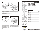

99-7400
INSTALLATION
INSTRUCTIONS
TOOLS REQUIRED
Cutting tool
Phillips screwdriver
KIT COMPONENTS
Radio
Housing #1
Radio
Housing #2
Faceplate #1
Faceplate #2
Bracket Set #9
Bracket
Set #17
Bracket Set #12
Bracket #13
& #14
Equalizer
Dummy Plate
Shaft
Masks
Mounting
Tabs #18
Mounting
Tabs #3
Mounting
Tabs #8
Mounting
Tabs #1
Mounting
Tabs #7
Mounting
Tabs #5
Mounting
Tabs #16
Mounting
Tabs #6
APPLICATIONS
CAR PAGE
NISSAN
200SX 1980-83.............................................................................1
200SX 1984-88.............................................................................2
240SX 1989-94.............................................................................3
Axxess 1989-90............................................................................4
Hardbody Pickup 1986.5-93..........................................................5
Maxima 1982-84.......................................................................... 6
Maxima 1987-88.......................................................................... 7
Maxima 1989-91.......................................................................... 8
Pathfinder 1987-93.......................................................................5
Pulsar 1983-86............................................................................. 9
Pulsar 1987-90............................................................................. 10
Sentra 1982-86.............................................................................9
Sentra 1987-90.............................................................................11
Stanza 1982-86.............................................................................12
Stanza 1987-89.............................................................................13
15
INST 7400
7
8
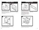
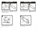
Locate the factory wiring harness in the
dash. Metra recommends using the
proper mating adaptor and making
connections as shown. (Isolate and
individually tape off the ends of any
unused wires to prevent electrical short
circuit).
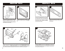
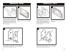
Re-connect the battery terminal and test the unit
for proper operation. Mount the head unit/kit
assembly to the sub-dash with those screws
previously removed in step #1.
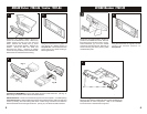
A
B
C
D
A) Strip wire ends back ½"
B) Twist ends together
C) Solder
D) Tape
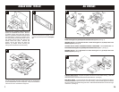
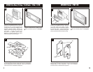
IF AN EQUALIZER WILL BE INCLUDED: Slide the aftermarket equalizer into the back of the
kit. Using the hardware included with the equalizer, mount the unit to the kit. (see Fig. A)
IF AN EQUALIZER WILL NOT BE INCLUDED: Snap the Equalizer Dummy Plate into the
opening in the kit. (see Fig. B)
6
Fig. B
Fig. A
1-800-221-0932 www.metraonline.com
© COPYRIGHT 2001 METRA ELECTRONICS CORPORATION
rev. 201202