


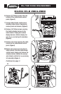
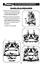
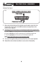


When using the Nav features of the interface you will need to connect the 2 pin
harness and run the 2 wires to the OBDII connector and connect them in the
position shown.
(Figure A)
7
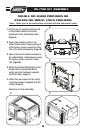
Re-connect the negative battery terminal and test the unit for proper operation.
9
8
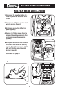
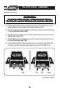
Reassemble radio and dash assemblies in reverse order of disassembly.
10
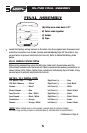
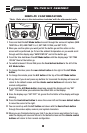
The following wires on the 10 pin harness are for the aftermarket radios that have navigation built in:
A. Connect the green wire to the parking brake wire of the aftermarket navigation radio.
B. Connect the pink /blue wire to the VSS or speed sense wire of the aftermarket navigation radio.
C. Connect the green/purple wire to the reverse wire of the aftermarket navigation radio.
NOTE:
Reverse output is NOT present on manual transmission vehicles.
1234
5
678
9 10 11 12 13 14 15 16
PINK WIRE
OBDII CONNECTOR FACE VIEW
PINK/BLUE WIRE
A
95-7510 FINAL ASSEMBLY
7
Continued from Page 6