


7
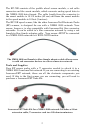
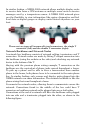
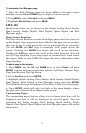
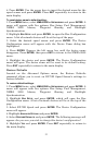
In this example, a new device is added to the NMEA 2000 bus by
installing a T connector between a T connector and a terminator at the
end of the backbone (network bus).
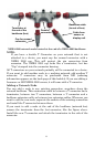
Additional Network Information
For more information on creating or expanding a network refer to the
NMEA 2000 network setup booklet, part number 988-0154-173, which
came packed with this document.
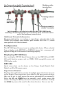
Configuration
The EP-70R Speed Sensor is not a configurable device. When selected
from a display unit, LMF-200 or LMF-400 device list, a message will
appear telling you if the sensor is working properly.
Displaying EP-70R Data
You can display EP-70R Speed Sensor data on the LMF-200 and LMF-
400 multi-function gauges and on NMEA 2000 compatible sonar and
GPS display units.
LMF-200
Speed sensor data can be shown on the Gauge, Single Digital, Dual
Digital and Fuel Manager pages.
Page Screen Rotation
The Page Screen Rotation consists of multiple pages that have been set
up for display. Once pages have been added to the page screen rotation,
they can be set to scroll across the screen automatically or manually.
Press the
UP and DOWN keys to manually scroll pages across the
screen. Pressing the
UP key moves the scroll in one direction. Pushing
the
DOWN key moves the scroll in the other direction. You can use the
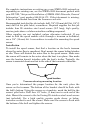
Existing network
node
Attach
terminator at
end of bus
Use T-connector or double T connector to add
device to bus (maintaining linear architecture)
Backbone cable
to rest of bus
Devices connect to
double T connector