


3
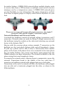
For complete instructions on setting up a new NMEA 2000 network or
expanding an existing one, see the NMEA 2000 document packed with
your EP-70R, "Setup and Installation of NMEA 2000 Networks, General
Information," part number 988-0154-173. If that document is missing,
it can be downloaded free from the Lowrance web site.
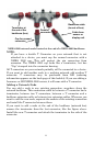
Recommended tools for this job include: drill, 7/8" (22 mm) drill bit, 1/8" (3
mm) drill bit for pilot holes, screwdriver. Required supplies for this job
include: four #8 stainless steel wood screws (3/4" long), high quality,
marine grade above- or below-waterline caulking compound.
Other supplies are not included, unless otherwise indicated. If you
want to feed the speed module cable through a transom or bulkhead,
use a 3/4" (19 mm) bit. A screwdriver is needed for mounting the speed
sensor.
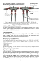
Installation
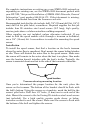
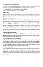
To install the speed sensor, first find a location on the boat's transom
where the water flow is smoothest. Don't mount the sensor behind strakes
or ribs. These will disturb the water flow to the speed sensor. Make sure
the sensor will remain in the water when the boat is on plane. Also make
sure the location doesn't interfere with the boat's trailer. Typically, the
sensor is mounted about one foot to the side of the transom's centerline.
Transom showing mounting location.
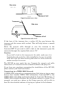
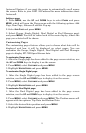
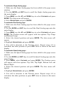
Once you've determined the proper location for the unit, place the
sensor on the transom. The bottom of the bracket should be flush with
the hull's bottom. Using the sensor as a template, mark the hull for the
screws' pilot holes. Drill four 1/8" holes, (3 mm) one in each end of the
slots. Mount the sensor to the hull using #8 stainless steel wood screws
(not included). Use a high quality, marine grade above- or below-
waterline sealant to seal the screws. Make sure the sensor is flush with
the bottom of the hull and tighten the screws.
good location