13
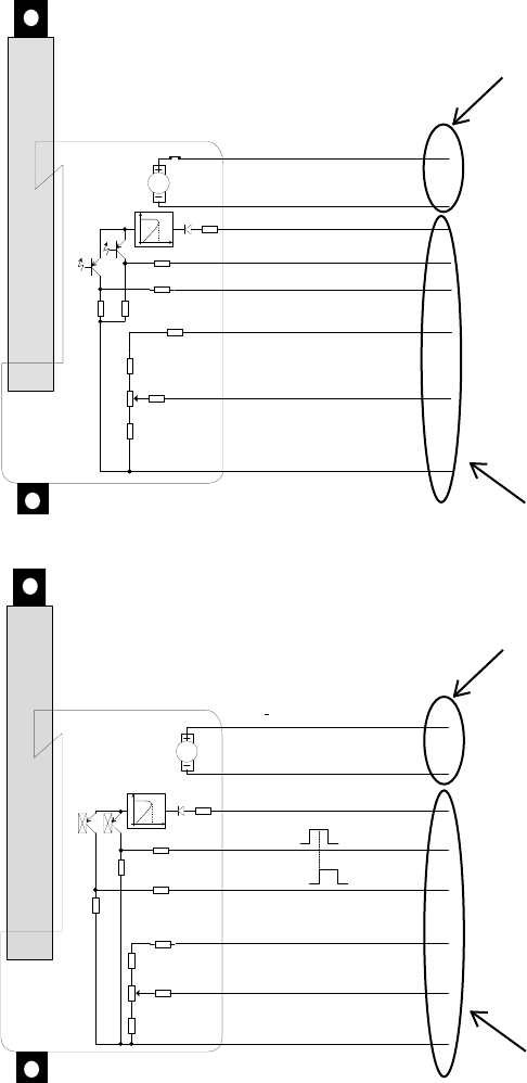
Connections diagram: For 36xxxxx2Pxxxxxx and 36xxxxx20xxxxxx:
5 K 6
5 K 6
1 0
1 K
1 0 K
0
0
E n d
IN
E n d
O U T
B ro w n
B lu e
R e d
Y e llo w
G re e n
W h ite
V io le t
B la c k
M o to r P o w e r + /- ( o u t / in ) 1 2 V /2 4 V /3 6 V
S u p p ly + 1 2 v to 3 6 V
E n d IN
E n d O U T
+ 1 0 V e x ita t io n
0 - 1 0 V O u t
G N D
P C B : 0 0 L A 3 6 W P E - C -X
+
-
24V
80 m A
Signals OUT
1 0
1 0
0
Power cable
Signal cable
Connections diagram: For 36xxxxx2Hxxxxxx
5 K 6
5 K 6
1 0
1 K
1 0 K
0
0
A
B
B ro w n
B lu e
R e d
Y e llo w
G re e n
W h ite
V io le t
B la c k
M o to r P o w e r + /- ( o u t / in ) 1 2 V /2 4 V /3 6 V
S u p p ly + 1 2 v to 3 6 V
H a ll A (E n d IN )
H a ll B (E n d O U T )
+ 1 0 V e x ita tio n
0 - 1 0 V O u t
G N D
P C B : 0 0 L A 3 6 M H P -X -X
+
-
24V
80 m A
Signals OUT
1 0
1 0
1 0
Power cable
Signal cable
Note:
If you wish to
use the end-stop
signals, you will
have to keep
power on the
brown and blue
wires, otherwise
the signal will be
lost.


