


206-4050-A
8
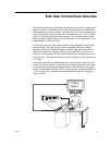
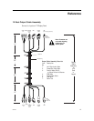
Installer Connections Contd.
After completing connections between the RJP, the TV display panel and other
resources, be sure the installer menu items have been updated to enable the RJP.
Installer Menu item 040 Auto Camport needs to be set to 000 and 093 RJP
Available needs to be set to 001. (See TV installation guide for complete instruc-
tions on new TV installations.) A brief description of each of the available RJP
connections is provided below.
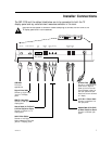
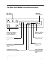
USB Output Port
For future applications--e.g., digital cameras and flash drives.
Digital Video Output
Connect to digital video input on TV display panel to allow the end-user to show
DVD’s high-resolution digital video on the in-room TV.
PC RGB Output
Connect to RGB input on TV display panel to allow the end-user to show a com-
puter/Laptop image on the in-room TV.
Control 8-Pin RJ-45 Output Port
Connect to RJP port on TV display panel for control and power supply for the RJP
multi-media interface.
Left-Right Audio/Video Output Jacks
Connect to Left-Right Audio/composite Video inputs on TV display panel.
Network Port (8-Pin RJ-45)
Connect to LAN wall jack, if available. Allows the end-user to access the LAN
(local area network) server of the institution.
Phone Port (6-Pin RJ-11)
Connect to telephone line wall jack. Allows the end-user, using a computer
modem, to connect to their ISP (Internet Service Provider) to access the Internet
through a local phone line.
AC Power Cord (Installed on RJP)
Connect to standard 120V 60Hz AC power outlet.
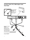
(Four 120 Volt 60 Hz AC power outlets are provided for the end user.
However, 7 Amps. is the maximum combined current allowed for the AC
outlets.